robb
Sergeant

Posts: 19
|
Post by robb on Apr 28, 2020 9:55:15 GMT 12
Here the ply lay-up is almost completed.  P1030932 P1030932 by Robert Brittenden, on Flickr And here the first of 50 Paulownia strips is being glued to the ply. Each strip is 50x12 mm and is tapered to match the profile of the fuselage. They are then edge-routed with one side concave and other convex. The strip is then steam-bent to shape and glued. (This technique is used in the strip canoe construction method.)  P1030948 P1030948 by Robert Brittenden, on Flickr There are 'only' 25 more strips to attach...then I can start all over again on the RH side. When finally joined together, the two halves will be covered with a thin layer of polyester and woven glass matt. The total thickness of the 'skin' will be 16mm- about the same as on the 'real thing' The markings sketched out show where the cockpit opening and wing 'stubs' will be. I have made so much progress over the lock-down period that I think I will have to self-impose another one! 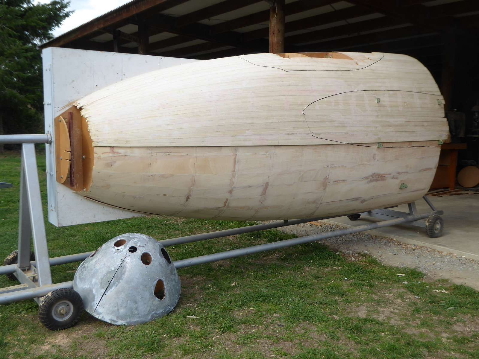 P1040063 P1040063 by Robert Brittenden, on Flickr |
|
|
|
Post by baz62 on Apr 28, 2020 9:59:50 GMT 12
That's going to look fantastic when its finished Robb..inside and out. Where abouts are you?
|
|
|
|
Post by ZacYates on Apr 28, 2020 13:08:05 GMT 12
Amazing work Robert! Wow!! Thank you for sharing.
|
|
axelford
Squadron Leader
I have visited 13 Plane wreck sites and counting, happy to help with info!
Posts: 120
|
Post by axelford on Apr 28, 2020 16:30:55 GMT 12
Looks great, what paint job is it going to have?
|
|
|
|
Post by Venomnut on Apr 28, 2020 19:01:40 GMT 12
That is really impressive Robert! A huge undertaking there with really high quality results. Well done.
|
|
robb
Sergeant
Posts: 19
|
Post by robb on Apr 28, 2020 21:07:31 GMT 12
Thank you all for your comments...
baz62: I am in North Canterbury, probably not more than a days march from you?
axelford: aha! regarding the colour choice, I may well defer to those with far more knowledge of such things!
Venomnut: I am also impressed with the fine restoration work that you are doing on the dH 'family member'
|
|
|
|
Post by Dave Homewood on Apr 28, 2020 22:06:27 GMT 12
Really extraordinary work there Rob. baz62: I am in North Canterbury, probably not more than a days march from you? So that's two days by Auster? |
|
|
|
Post by johnnyfalcon on Apr 28, 2020 22:29:27 GMT 12
Unless you have to pull it on a trailer...
|
|
|
|
Post by baz62 on Apr 29, 2020 10:08:20 GMT 12
Ahhhhhh not trailers please no!  Well Robb if you are up for visitors after we are out of lockdown I'm sure there is a few of us who would love to admire your handiwork. |
|
|
|
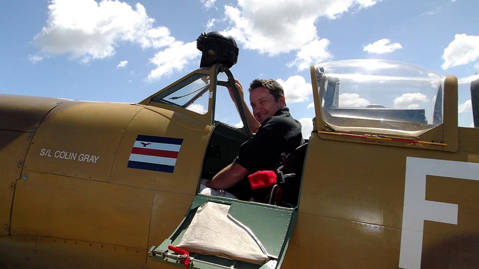
Post by agile on Apr 29, 2020 20:32:27 GMT 12
Rob was kind enough to let us have a sneak peek a few months ago. His workmanship is really something:  Having never actually been in a Mossie cockpit with a seat in it (I don't get out much), sitting in the seat (and making all the obligatory noises) I was already struck by how cramped it is- and that's without the cockpit sides or the nav sitting next to me. He has also been very genererous in his support of our project, making masterpieces like this junction box:  |
|
|
|
Post by Venomnut on Nov 30, 2020 17:16:31 GMT 12
Left side repair complete apart from the tapered doubler below the armoured fillet. Belly repairs next on the to do list. I might have to nickname it patches.  IMG_9254 IMG_9254 by Jason Mills, on Flickr |
|
|
|
Post by Dave Homewood on Nov 30, 2020 18:43:59 GMT 12
That's looking brilliant Jason!
|
|
|
|
Post by Dave Homewood on Nov 30, 2020 18:55:17 GMT 12
How is the Mossie cockpit coming along, Robb?
|
|
|
|
Post by ZacYates on Nov 30, 2020 22:18:37 GMT 12
She's looking amazing Jason, great job!
|
|
robb
Sergeant
Posts: 19
|
Post by robb on Dec 1, 2020 21:21:50 GMT 12
How is the Mossie cockpit coming along, Robb? Steady progress has been made over the intervening period. The completed LH shell-half has been released from the frame, and the fairing, sanding and painting of the internal wall is done. Flight controls are being fitted, along with instrument panels etc. I should start making the RH shell-half early next year. I will put more pictures then. |
|
|
|
Post by Dave Homewood on Dec 1, 2020 22:14:41 GMT 12
Sounds great!
|
|
|
|
Post by Venomnut on Dec 3, 2020 17:39:59 GMT 12
I decided to tack the damaged right intake from VNM1 on just to get a feel of how I'd like the project finished, once I can source some undamaged intakes. The 2x4 brace is appropriately positioned where one of the fence posts hit during the overrun.  IMG_9256 IMG_9256 by Jason Mills, on Flickr The nose bay is nearly complete. The main items missing are the IFF unit (where the cannon plugs are) and one of the radio units. When I purchased the project it had no original equipment in this bay. All parts in here, including the mounting frame and base plate, were sourced from one collector in Switzerland. The IFF units seem to be hard to get but some have made it into civilian hands.  Nose bay Nose bay by Jason Mills, on Flickr If anyone has leads on a Swiss Venom/Vampire IFF unit they're willing to sell, please let me know. Cheers. |
|
|
|
Post by Dave Homewood on Dec 3, 2020 20:32:09 GMT 12
Superb stuff Jason! We have some very clever people on this forum.
|
|
robb
Sergeant
Posts: 19
|
Post by robb on Aug 27, 2021 9:53:45 GMT 12
FBVI replica-cockpit/ simulator project 2021  P1040084 P1040084 by Robert Brittenden, on Flickr The front end of the LH half shell, after being released from the rotary base.  P1040103 P1040103 by Robert Brittenden, on Flickr Out in the open with the internal templates removed.  P1040196 P1040196 by Robert Brittenden, on Flickr After much hand sanding, marine faring-compound was applied requiring more sanding... The area of grey paint was a test of a high-build primer.  DSCF0523 DSCF0523 by Robert Brittenden, on Flickr Marking out and fitting the ferrules - there will be about 80 in total. The top surface of the 'bench' is set at the fuselage datum. The vertical positions given on the dH drawing are referenced to this.  P1030004 P1030004 by Robert Brittenden, on Flickr The next few pics are of some of the hardware that was made a while ago: Front view of the 'hydraulic'valve levers that operate the flaps, undercarriage, and bomb doors. In operation, these levers quickly flick back to the centre position when their associated hydraulic rams reach their maximum or minimum travel.  P1020992 P1020992 by Robert Brittenden, on Flickr The 'hydraulic' valve levers were machined out of steel bar and the knobs from aluminium.  DSCF0441 DSCF0441 by Robert Brittenden, on Flickr Pneumatic actuators(three position) were made to simulate the action of the hydraulic valve levers. The photo shows one set of parts and one fully assembled cylinder.  P1030580 P1030580 by Robert Brittenden, on Flickr A 'control column kitset'...every item shown here, apart from the bearings and the special chain ($30+ per foot!), was made from scratch. Three of the items are 'investment cast' aluminium using 3d-printed PLA patterns, and two are by the 'old school' method of sand casting from wooden patterns. I had initially made extensive measurements of HR339's control column at Ferrymead (thanks again to Dag and Alex) but later on I obtained and worked off the original dH drawings bought from the HARS digital archive.  DSCF0614 DSCF0614 by Robert Brittenden, on Flickr More recent tasks are the conversion of the Blind Flying Panel instruments. Like every other item in the cockpit, they will need to be computer controlled. This entails removing the 75-year old internals and driving them with RC servos or stepper motors. The Altimeter here shows the redundant (barometric) mechanism beside the custom built gearbox. The gearbox has three concentric output shafts with 1:1 1:10 and 1:100 ratios - so all the hands can whizz around in the correct way.  DSCF0639 DSCF0639 by Robert Brittenden, on Flickr The finished Altimeter. A stepper motor drives the hands via the (internal) gearbox. The 'barometric pressure' setting knob now operates a 10 turn potentiometer. Of all the BFP instruments, only the Gyro Compass remains to be converted.  DSCF0651 DSCF0651 by Robert Brittenden, on Flickr Behind the control panel it's becoming a bit of a jungle. A lot of connections and cabling to the 'outside world' is yet to be started.  DSCF0650 DSCF0650 by Robert Brittenden, on Flickr The vacant space below the 'wing deck' will house pulleys, cables and the associated control loading ('force feedback') system. This will need to be more or less completed before joining the right-hand half-shell. The open space above is where I will need to make a canopy...unless one should happen to turn up at an op-shop somewhere   DSCF0655 DSCF0655 by Robert Brittenden, on Flickr Meanwhile, the right-hand half-shell is 'standing by' to be released...maybe it will be fitted by next year's update?? Over and Out. |
|
|
|
Post by Dave Homewood on Aug 27, 2021 10:31:03 GMT 12
Fantastic progress Rob!
|
|


 Well Robb if you are up for visitors after we are out of lockdown I'm sure there is a few of us who would love to admire your handiwork.
