|
|
Post by ZacYates on Jun 27, 2021 15:36:36 GMT 12
I always enjoy seeing the Hudson updates, thank you Denys.
And thank you Alex for sharing the Mossie update. It makes my head spin a little seeing the work that can go into a single part.
|
|
|
|
Post by denysjones on Jul 3, 2021 21:19:45 GMT 12
This week starts off with the solution to another one of the several years old puzzles from the part shelves being something that I'd long ago concluded that it was for some form of clip-on point for a belt or harness of sorts but the location for it was defying resolution.  The other week Mike Nicholls sent me some scans of Hudson photos, mostly interiors, that were found amongst John Smith's materials and this Tuesday's foul weather provided the opportunity to pore over them. They were very dark prints so required a bit of adjustment and out of 12 photos one caught my eye showing something I've not spotted in any other Hudson or photo. It was of the rear of the cabin looking aft and seemingly focused on the vertical camera installation that goes by the second to last window port side. Of course once I saw it and then looked back at other shots from other sources it can just be discerned when you know what you're looking at/for namely the rod running through the shot centrewise.  I wasn't sure who would use it though as I thought the ventral gun position, to the starboard side, had seatbelt locators in it but that turns out to be false so I guess that's it. Anyway today 2035 received another fine detail. Big thanks Mike!  The other foremost task of the day was to temporarily fit the pulley gang, from recent weeks' reports, behind the firewall. It attaches at the rear and top to two fittings on the vertical face of the wing and at the bottom has four brace struts that go to two brackets on the rear engine frame. Our unit had had the four braces cut just below where they attach to it so I can salvage the end pieces from the remains. I'd been pondering what to do about the bottom ends and to my delight the other day came across three of them (where's the fourth?). Thus today I needed to see the unit in place and aligned as it has to be for the cables to run so I could measure the centre to centre of the attachment points in the pulley frame and on the rear engine frame and proceed to make same. Hopefully more next week folks..cheers |
|
|
|
Post by curtiss on Jul 4, 2021 8:45:45 GMT 12
Great that the photos were useful - thanks to John Smith.
|
|
|
|
Post by agile on Jul 4, 2021 8:54:50 GMT 12
I always enjoy seeing the Hudson updates, thank you Denys. And thank you Alex for sharing the Mossie update. It makes my head spin a little seeing the work that can go into a single part. Hey Zac, our pleasure. With regard to the work that goes into some parts, sometimes it's difficult not to silently scream at the designers 'don't you know there's a bloody war on'. |
|
|
|
Post by denysjones on Jul 11, 2021 12:47:33 GMT 12
A day of fit and fiddle on the Hudson front this week. During the week I started work on the end fittings of the four brace struts for the pulley gang and based on the measurements taken during last week's trials made what hopefully would be the inboard pair. Given the end pieces had those -2 and -3 ends to their P/Ns as a first try I took a punt and made one strut with -2 both ends and one with -3. I then tried them with the -2's in the upper position and the -3's on the bottom and put the gang in place and as things turned out they'll do the job nicely.  So with them in place the outboard pair's measurements could be taken. There turns out to be a 4inch difference in length. So they'll get done next. My other plans for the day got altered mid morning when Dagy arrived with presents. He's building a new house and from his heat pump installer he'd obtained, for the right price of course, two coils of the 3/8inch copper tube I'd been after to make the connections from the exhausts to the analysis coil and return. So I couldn't restrain myself and leapt into that task to see how it would turn out. We have no photos of this stuff nor do the tubes appear in the tube bending tables. All I have to work from is the diagrams in the IPC which could well be somewhat loose interpretations of the real thing. As a result even the diameter of the coil was a guesstimate but it fills the mounting gap and looks right so that's the first of five tubes made for the port unit. 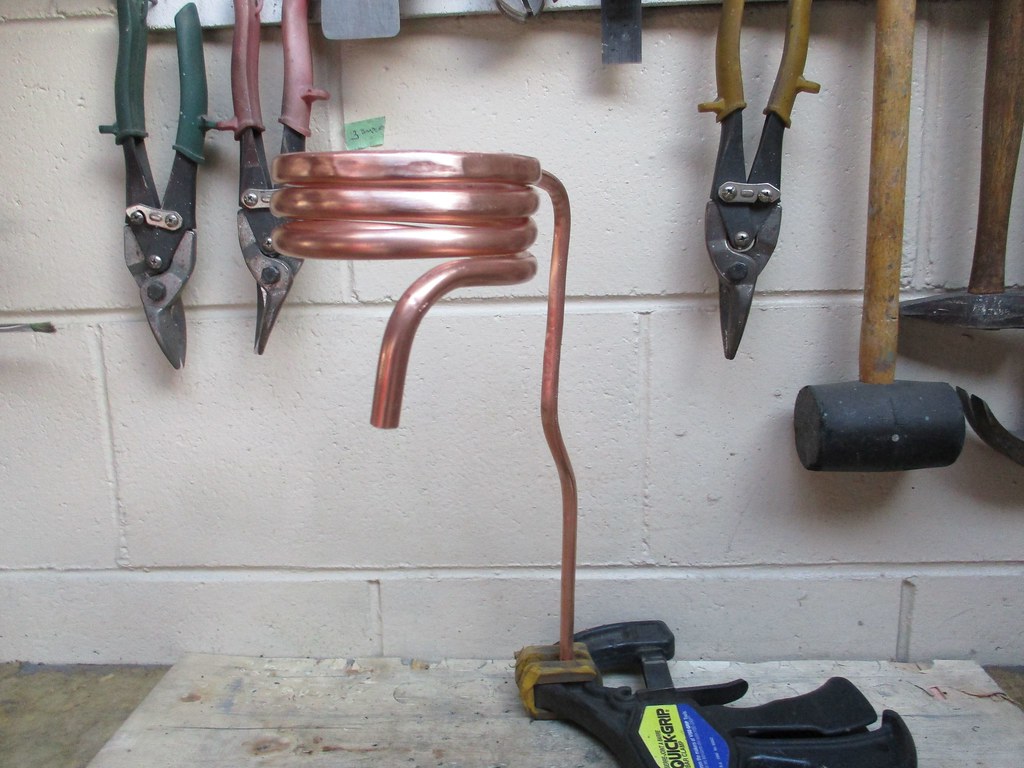 cheers |
|
|
|
Post by davidd on Jul 11, 2021 15:17:22 GMT 12
Lovely bright copperwork, great (and heroic) work Denys!
|
|
|
|
Post by aircraftclocks on Jul 11, 2021 16:44:05 GMT 12
Looking at books on the subject of Cambridge aero mixture indicators, advises the the 3/8" O.D annealed copper tubing, minimum non-insulated length = 4 ft. In another it says minimum of 5 ft.
|
|
|
|
Post by oj on Jul 11, 2021 20:04:38 GMT 12
I'm a bit thick about these copper tubes. Are they part of an engine exhaust gas analyser system?
Did exhaust gas "bleed-air" pass through them or were they a muff to go around the exhaust pipes to give an EGT reading?
|
|
|
|
Post by aircraftclocks on Jul 12, 2021 1:19:59 GMT 12
The coil of copper tubing is to cool the incoming exhaust gases. The temperature must not exceed 125F (51C) as it enters the input filter chamber.
The system must also not be exposed to freezing temperatures as ice could form from the condensate thus stopping the gas flow.
|
|
|
|
Post by denysjones on Jul 12, 2021 9:13:44 GMT 12
That info re the lengths is interesting thanks aircraftclocks. As I said all I had to work from is this diagram from the parts book which is clearly indicative only, for example there is no way the plumbing is in front of the frame as the firewall is firmly attached thereto.  I guessed the diameter of the coil at somewhere between 3 and 4inches, based on where it seemed it would fit. I then hunted around for a suitable object to wrap tubing around to form it and found an offcut of a billet of steel that was 3 1/2 in diameter and so ran with that. After a bit of schoolboy maths I estimated the length needed to make three turns and then ran a rough measure along where I thought things would most probably actually run. I decided that the joiner shown below the clamp block labelled 15 would probably have actually been along the diagonal strut (as there is a clamp fitting on it that I guess is probably to attach the tube with). This all gave me a length of about 30inches so I cut off 36 and will shorten it on that diagonal point. With the second stage which I guess will work out around the 20inch mark that sits nicely in the defined range. cheers |
|
|
|
Post by oj on Jul 12, 2021 19:55:32 GMT 12
I still don't know what the purpose is.
The incoming exhaust gases are cooled before going into what, and what does the what do?
|
|
|
|
Post by aircraftclocks on Jul 13, 2021 0:14:34 GMT 12
The following is from the book:
GENERAL DESCRIPTION
FUNCTION.
By analysis of the exhaust gas this instrument shows the mixture on an indicator scaled in fuel-air ratio with a range of .11 to .066.
PRINCIPLE OF OPERATION.
Operation of the instrument is based on the well known thermal conductivity principle wherein four platinum spirals forming the four arms of a Wheatstone bridge circuit are employed, two being exposed to the gas under test and two being exposed to a gas of known heat conductive capacity. The known or "standard" gas in this instance is moisture saturated air which is contained in the small chambers where the "comparison" spirals are located. The spirals are heated a definite amount by an electric current and they will remain in balance as long as they are surrounded by gases of similar conductivity and thus are at like temperatures. However, when the "test" spirals are exposed to exhaust gases of different mixtures, their temperature will be changed and the bridge will become unbalanced, resulting in a deflection of the galvanometer pointer to an extent comparable with the variation in the constituents of the gas and in this manner it is possible to determine the mixture ratio directly.
COMPONENT PARTS.
The complete instrument comprises:
1. The required number of analysis cells, one for each engine.
2. One indicator unit containing an independent scale and pointer for each cell, thus affording simultaneous readings for all engines, in addition, one duplicating indicator to furnish a duplicate indication for the second cockpit.
3. The necessary accessories for conducting a sample of the exhaust gas from the engine through the cell, including sampling nipples, copper tubing and rubber connectors, and,
4. In the case of single engine instruments, shielded cable to connect the analysis cell to the indicator. No cable is furnished with instruments for multi-engine planes as existing conduits are usually employed.
|
|
|
|
Post by oj on Jul 14, 2021 21:46:03 GMT 12
Thank you clocks.
As an avionics LAME I ought to have learnt about or encountered one of these over 30 years in the industry, but alas not so even though I am an analogue enthusiast.
The Wheatstone Bridge explanation made it clear immediately.
Thanks again. I am suitably re-edified.
|
|
|
|
Post by aircraftclocks on Jul 14, 2021 23:52:18 GMT 12
Oj
The book was written in the 40's, a bit before both of our times. I do not recall this system being explained in my Avionics training in the early 80's either. I just have a few books from the 40's.
|
|
|
|
Post by denysjones on Jul 17, 2021 21:44:59 GMT 12
First job this week was the flare pistol holder we received the other month (see May 22 page 25). This job necessitated some online research about dealing with hardened leathers. In the end I combined two seemingly popular methods namely a restorative wax type of substance which you work into the surface and the application of subtle heat. The former was kindly provided by the other half's shoe care provisions where a pottle of "Elephant Leather Preserver" came to hand, promising to fight various forms of damage but including dryness. The second treatment came via a fan heater. The holster has now resumed most of its original dimensions and flexibility and is temporarily packed with synthetic packaging foam, to hold it thus, and in the next weeks will receive a couple of further treatments. The general surface has cleaned up but I doubt that we can now recolour it due to the wax application so we'll leave it "as conserved". The new dome fasteners will eventually attach it to the original units in the cabin.  On the equipment bay front the first two pieces of analyser plumbing have been painted, along with clamps, and new rubber sleeves cut so they could go in today while the two mates for them to run down to the exhaust could be measured and bent up. As part of this the stay for the pipe feeding the ram air feed to cool the analyser was remade and positioned.  Also today saw the outcome of a recent roadie our newly rejoined member Dean did with his beloved the other weekend. On their return leg they hooked into Mayfield to a well known junk/curio shop, which was mentioned on the Forum some ago in respect of some C47 cowls. Whilst there Dean had a general fossick about and in a shed in the yard came across a couple of items he recognized to possibly be of interest to me (proof that his time in the RNZAF wasn't totally wasted!) If you look back to the post on page 21 of Nov 14th last you'll see that we'd received the second starter-feathering pump we needed but sans the pump portion and one such was the first thing Dean came across. Also lurking with it was a fuel filter we didn't need but was too good to pass up for the AC series plumbing items attached. In fact the elbow off the top will probably immediately be reused on the inlet port of the pump. So today Dean revisited and collected those. 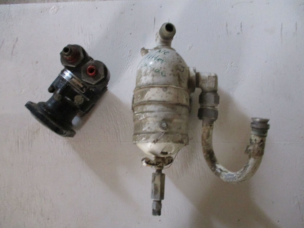 Also there was a pair of C47 oil coolers which it seemed a shame to leave there, especially as the owner has indicated that the business will soon be closing, but at $500 for the pair we had to pass. Just letting you know in case there are any interested parties out there. ttfn |
|
|
|
Post by agile on Jul 24, 2021 8:45:16 GMT 12
Last night members and their partners met for dinner at the Valley Inn Tavern to mark the 50th Anniversary of the foundation meeting of the Ferrymead Aeronautical Society on 23rd July 1971. It was a great opportunity to remember times gone by and absent friends, and to reflect on the Society's achievements - a unique collection, under cover (except the Wessex) and all done with volunteer power and fundraising.
|
|
|
|
Post by baz62 on Jul 24, 2021 14:44:49 GMT 12
Wow congratulations. 50 years and counting! I think the first time I visited was 1975. My mate and I cycled from our homes in Burnside to see the aircraft which were the Viscount,Hudson and LC47 all outside. To have virtually all the aircraft undercover bar the Wessex is a testament to the drive from the Ferrymead team. Well done.
|
|
|
|
Post by Dave Homewood on Jul 24, 2021 17:37:19 GMT 12
Congratulations to all involved!
|
|
|
|
Post by denysjones on Jul 24, 2021 19:41:53 GMT 12
To start this week's post something not directly to do with the nuts and bolts of the job. As Agile said last evening we had a celebratory dinner at our traditional watering hole, the Valley Inn Heathcote, to commemorate the 50years ago of the society, and it just happened to be that yesterday's date matched that when a public was called to be held at RNZAF Wigram where it was resolved to form the Ferrymead Aeronautical Society. Members past and present swapped more than a few tales of the escapades and achievements of the ensuing years and drank the odd toast to those and the people who made them happen and thought of how now with the advancement of years we might consider the foolishness of deciding to do what we have done!. Meanwhile back at the coal face in Hudson land today the second pair of two pipes completed the gas analyser installation. This shot is looking down from above the bay and you can see the two black pipes running down on the left and then across the bottom to make their connection with the exhaust trunking. The large pipe running across the lower of the shot with the black band on it is the oil feed line from the Y-valve (see page 24 April 10).  and also the newly recovered, and now rejuvenated and outfitted, feathering pump was installed. 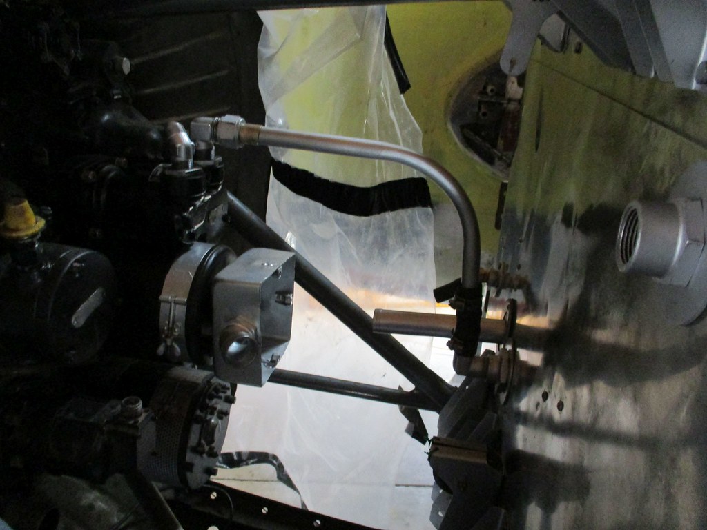 The second fitting on the pump takes a line from it forward to the pitch control on the front of the engine and so the latter part of the day saw more rummaging took place in the piles of assorted plumbing in the hopeful quest for pieces that might perhaps lurk there which would connect it to said prop governor. cheers |
|
|
|
Post by denysjones on Jul 31, 2021 20:29:47 GMT 12
First task on the agenda for today was to locate the flare pistol holder to ensure all the dome fasteners engage etc. There should be two more domes on it but the available size appears to be a fraction larger than that of old and so impinges onto the actual holster so for the moment it is a hang-fire wip. FYI above and slightly to the rear of the holster you can see the two fittings, one out of the side wall and one on the curve of the roof, into which the pistol locks for firing.  Next back to the engine bay and in went the pulley gang...things are getting crowded in there and there's still more to go.  Above the bay is another puzzle in the form of the mounting plate, with four holes in it, currently in grey primer. Said holes are for Lord mounts but what they hold is the puzzle for the moment. What goes here that needs vibration mounts?  Meanwhile down in the hangars what's going on here?  Due to Covid we're blessed with the company of one of our very early members now a resident of the Scott Polar Research Institute at Cambridge University, one Dr Bryan Lintott. Whilst marooned here he's been putting his time and equipment to use, ably assisted by new younger member Reece, mapping the story of the various colour schemes the LC47H has worn and still does, layered one on top of another. By taking multiple photos from various angles and feeding them into smart software it uses the Lidar technique to peel off the layers and so he's been "uncovering" such things as the cartoon of "Mutha Goose" she once wore. All of this is in preparation for work to restore the old girl in time for the major celebrations of DeepFreeze history set for 2025-26. ttfn |
|