|
|
Post by johnnyfalcon on Nov 5, 2022 18:05:09 GMT 12
Fascinating and humbling presentation once more Alex. Thank you!
|
|
|
|
Post by ZacYates on Nov 9, 2022 8:44:39 GMT 12
Hear hear. Always a thrill to see the latest goings-on.
|
|
|
|
Post by denysjones on Nov 13, 2022 19:58:31 GMT 12
A quiet day on site yesterday. 633Sqn was just represented by Angus, busy makging wiring bits and pieces as he does, and Dag cursing and muttering about the intricacies of the fittings on the sills of the nose gun bay of the Mossie. Team1058 were busy doing their thing and Dave was cleaning the control pedestal to go back in the Sunderland cockpit. Following on from the tubes made last week, for the hydraulics from the firewall to the engine pump, I had moved on during the week with the next pair and so now here in amongst the increasingly involved area forward of the starboard firewall are the quartet of tubes from the manifold (left centre rear as you see the photo) down across the photo to the hydraulic pump in the centre foreground.  Now to move to the lines from the rear of the firewall back along the leading edge of the centre section and into the fuselage and the system feeds there. The afternoon also allowed a start to be made on the two feeds for that purpose on the port side (so much easier I find to do things in pairs side for side!) :-) |
|
|
|
Post by ZacYates on Nov 14, 2022 7:37:49 GMT 12
A quiet day on site yesterday. Any progress is good progress! Thank you for the update, Denys. |
|
|
|
Post by davidd on Nov 14, 2022 10:13:46 GMT 12
The exact location of HR339's final resting place was with the Goodwin farm on Starvation gully road (not far from the sea shore, the public hall, the old school (closed about 2005/6), church, etc.), although the nose section came to rest separately on property of Arnaud McKellar at "top end" of Pigeon Bay on the main road, and near the old Kukupa School which closed down in 1949. Some parts (including rear fuselage, engine nacelles, tail cone, complete undercarriage) were stashed in the Goodwin's huge seed shed right beside the road, so remained in excellent condition, while the forward fuselage was located outside, on the McKellar property out behind the share milker's cottage on (I think) the east or SE side of the main house, so suffered severely from the elements. The main wing section was cut into about 4 sections and was placed under the large macrocarpa trees near the Goodwin's seed shed. I'm thinking back to about 1958/60 here with reference to the forward fuselage location.
|
|
|
|
Post by agile on Nov 14, 2022 18:01:58 GMT 12
Hi David. Thanks for that. We've actually been back to the big shed from which the bits emerged (the new owner of the Goodwin's property found a few more bits of Mossie).
My colleague is working on Arnaud McKellar's place at the moment (that's the property that was leased to a Duxbury at some stage) and is under strict instructions to keep an eye out for bits of aeroplane, although I'm quite sure it's all gone - Arnaud certainly thinks so.
|
|
|
|
Post by agile on Nov 15, 2022 7:58:09 GMT 12
The Duxburys in question were John Morgan and Alexander, as it turns out.
|
|
|
|
Post by davidd on Nov 15, 2022 10:44:23 GMT 12
Both those Duxburys were brothers of my grandfather (who was the youngest born of that generation), and I think Alex Duxbury also farmed the McKellar farm in the early days, might have lived in the cottage I described (which may or may not exist any longer). The big house and farm were originally owned by a family from Venice of all places, by name of Badua. Strangely I also have a nephew in his late 20s, called Alex Duxbury, born in Brisbane and now married, still living there, don't think he even realizes that he had an ancestor of same name.
|
|
|
|
Post by Dave Homewood on Nov 26, 2022 22:45:33 GMT 12
Well Bill was a foundation member of the NZ Permanent Air Force, a founder of the Aviation Historical Society, and builder of a Heath Parasol as well as collector of reputedly the finest collection of vintage phonographs in the Southern Hemisphere which he bequeathed to the Park. ttfn A contrast in sizes after the small machine built by Leading Aircraftsman W. S Dini, of Christchurch, had taxied beneath the huge wing of the Southern Cross monoplane. Mr. Dini is standing in front of the smaller machine. After first being taken up by Mr. R. Kirkup. of Auckland, the aeroplane was then flown, and the controls tested for stunting purposes, by Sir Charles Kingsford Smith. NEW ZEALAND HERALD, 27 MARCH 1934  |
|
|
|
Post by denysjones on Nov 30, 2022 18:18:47 GMT 12
I've left you folks updateless for a few weeks as it's just been more Hudson pipeworks, though the end is nigh! Given that refers to the Hudson engine pipe stuff my mind turned to another piping job that awaits my attentions. As when you're in the swing of something it is silly not to carry on especially as it is for the Hudson anyway. It is in the Boulton & Paul Type C turret. Then I suddenly realised that among the faithful who read these rambles there are probably quite a number who have not seen or heard the story to date of our turret, as it's not been dealt to on this thread, I thought it a good idea to set the scene with a wee history lesson. Apologies to those who have seen or heard this of old. Back in the dark early days of things in the 1970s or so Ross Macpherson donated us the two pieces of the cupola of such a turret that he had retrieved from a gentleman near Otaki. Each year it was used to grow said chap's pumpkins under. That was all we had until 2003 when we received the major parts of a unit from the B-24 project at Werribbee near Melbourne which was a major windfall as I've been told on good authority that there is something less than 20 known to exist in the world. The B-24 folks received a call asking if they collected the turrets off old aircraft and were told that if they wanted one they had to get to the caller's business that day and collect what had mysteriously turned up in his dumpster that morning. The pieces were collected and taken to the team's store where their secretary eventually came across them. It was he who recognised what they were and hence what aircraft they applied to. Knowing that I was after one he duly arranged to swap them with us. What arrived was a disassembled collection of bits in somewhat poor condition, including a second cupola. This, upside down, is the main chassis, for want of a better term, of the unit as it arrived. 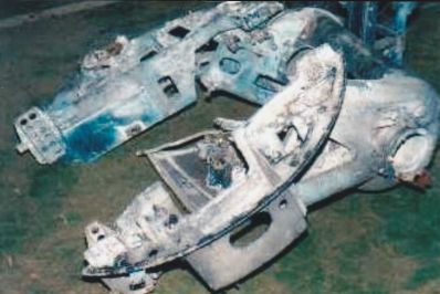 A couple of years later things had progressed to this level. Said chassis is now the other way up and the arch from one of the cupolas is now attached. A lot of work went into disassembling numerous needle bearing races where the grease had hardened and things that should turn or pivot simply just didn't.  After a few more years that has advanced to this stage along with the two halves selected to form the cupola alongside.  The lower main unit arrived minus one of the sides, which house the ammo boxes, and so at this time I was fabricating the other.  By 2018 we'd got to this stage with the upper and lower stages now attached to the base mounting and rotation ring. Numerous details parts, many sourced from other preservation groups back in the UK along with the AWM Canberra, are building up the whole unit.  But since then the poor old thing has been languishing while other matters have claimed precedence...but action is coming. |
|
|
|
Post by denysjones on Dec 3, 2022 20:41:11 GMT 12
As best as can be seen here in these two shots looking down on the rear area of the turret of a unit at RAF Hendon, the obvious void being filled by the gunner's body, on the left is the "hydraulic generator", otherwise best described as "hydraulic pump". That's the object top right of shot and you see the tubes running out around the left. 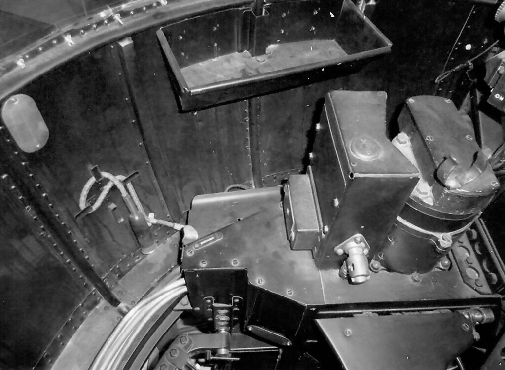 These go around the turret rim behind the gunner to the unit on the right hand side which is the hydraulic motor for obvious uses.  The plumbing of all of this is shown by this diagram from one of the manuals, some items being the above the deck so to speak in the shots above and others below. All in all there are runs labelled A to G . 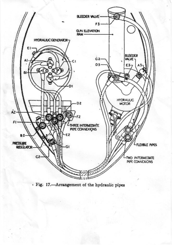 The end pieces of the tubes are referred to as "banjos" for simple resemblence reasons. The best count at the moment is that we needed 22 of these and cost and availability has led to me turning to resin casting them from a mould made from an example we held. From photos we have of a turret above at Hendon the tube runs appear to be brass while other turret photos we have show them to be painted black so who knows! For reasons of finances, availability of materials, and practicality related to material malleability I've turned to running them in copper and so will be painting them black like those I've seen in other turrets. So on the basis of the above diagram from the manual of the runs.....wish me luck it's a long job ahead! |
|
|
|
Post by denysjones on Dec 11, 2022 20:07:49 GMT 12
One of the first jobs of the morning yesterday was on the drill press drilling holes in the resin castings made from a mould of a hydraulic systems banjo end. There are 22 of these need for the plumbing of the turret so it is very much a work in progress but the first eleven are ready to go while another eight are work in progress. Herewith a sample knock-up of what these things are about for those not au fait with them, and another just cast in the mould today leaving two more to pour. 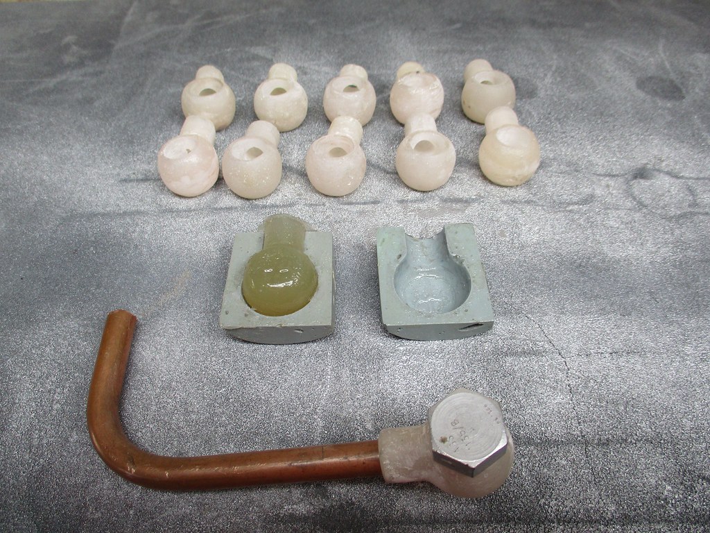 Then I moved onto yet more plumbing puzzles. Over the week I'd got the crossfeed pipes from the fuselage systems area out to the engine bays for the fuel feeds done and so in they went (red bands signify fuel lines) adding to the population across the wing front.  However there's still more to do and I moved on to investigate two elbow connections on the wing leading edges. You can see in this photo in the centre ground there are three elbows of different sizes pointing away from the viewer. There is a fourth at the top which is obscured. It and the top one of the three visible are the feed and return for the undercarriage retraction but the time has come to find out what the other two are.  Fortunately for me in the port undercarriage bay I found the in situ answers to be the runs for the emergency undercarriage extension and the brakes. The starboard items were long gone as that centre section is the one that had been buried in the cesspool. Here they are coming down from the upper right of shot and arriving at the fairlead attached to the lower cross member. The smaller diameter one is the emergency undercarriage extension and the larger the brake line. 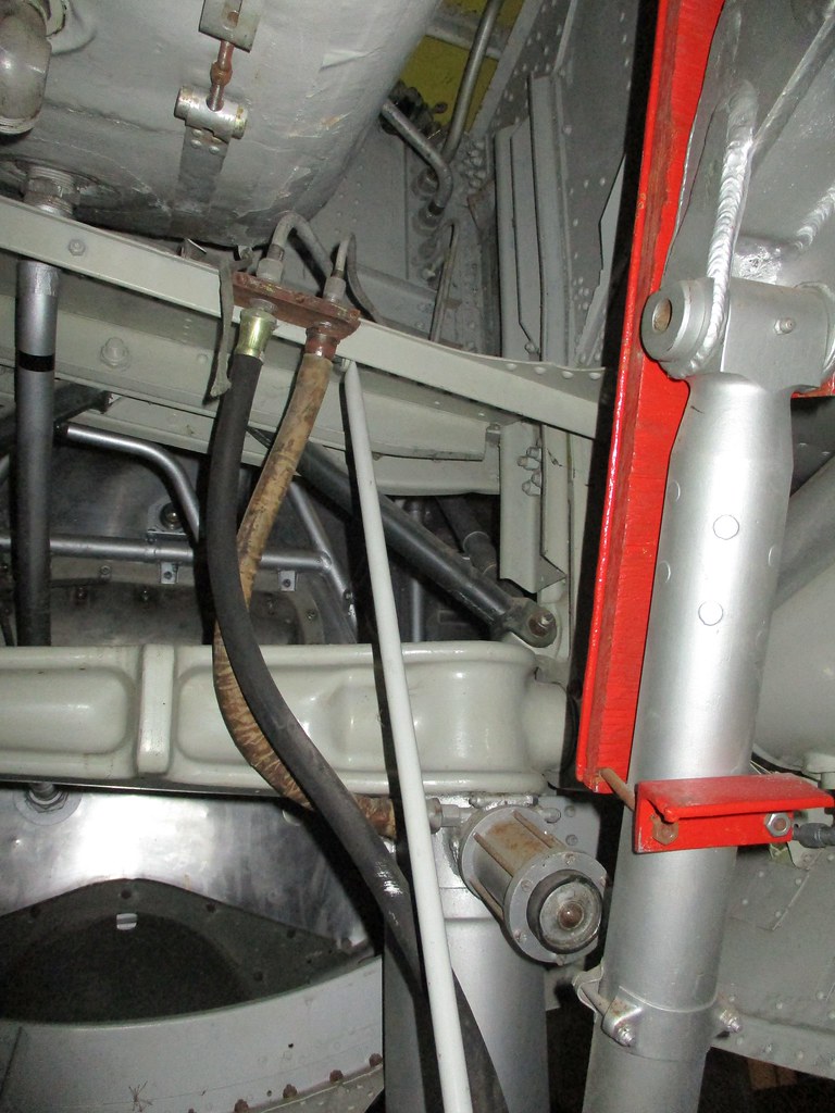 Here's the diagram for the emergency undercarriage extension.  The elbows are the right angles joining pipes 7-10 and 9-11. The items in the upper portion of the diagram portray this unit located on the forward right side of the floor in the w/o's den.  The presence of the original 11 and 13 in the port enabled me to bend up 10 and a fossick in the parts piles luckily turned up an original 12 (it and 13 are actually hoses) Now I've got to sort out 7,8 and 9 and where they fit.... |
|
|
|
Post by davidd on Dec 12, 2022 7:42:53 GMT 12
You are a mighty warrior Denys!
|
|
|
|
Post by ZacYates on Dec 12, 2022 10:10:33 GMT 12
Hear hear!
|
|
|
|
Post by denysjones on Dec 23, 2022 10:24:01 GMT 12
Last Saturday's programme included picking up on the connections from the emergency undercarriage extension pump. A quick grope around under the floor panel adjacent to the pump's location in the w/o's bay confirmed that there was a tee joiner under there and that one leg was pointing forward while another was connected onto something that felt it matched the relief valve in the diagram from my last post. I then moved forward in the a/c and looking back under the steps that lead down to the nose office there was the tee and a tube on it coming through the front shear beam of the wing which passes through the a/c at this point. 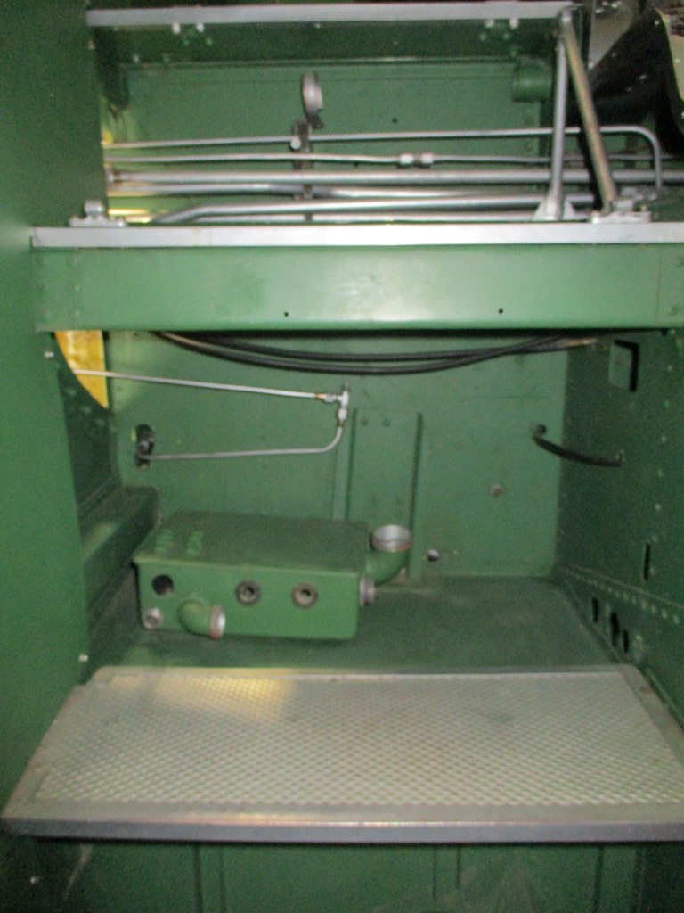 It appears that the tube is a combination of items 5 & 6 on the system diagram. It also became apparent for physical reasons that in reality the now attached tee (between tubes 7 & 8) had to be orientated as you see I've put it. Connecting it out to the starboard as it now is was dictated by where the feed coming in from that side fitted while the one heading to port looks like its only option involves going upwards and then turning across the fuselage....but that's for the next day's agenda (Xmas eve hopefully). |
|
|
|
Post by denysjones on Dec 31, 2022 20:33:51 GMT 12
A happy new year to all of you who take the time to view my scribbles here and offer words of praise and even more so to those who kindly throw some funds our way via our GiveALittle page.
All the best for 2023 and rest assured you'll find fresh rambles here.
Thanks also to Dave H for instigating this platform for us to interchange on and so avoid some of the darker sides of things like Farcebook.
cheers
|
|
|
|
Post by baz62 on Jan 1, 2023 9:18:39 GMT 12
Same to you and all the team at Ferrymead. Always look forward to Ferrymead updates!
|
|
|
|
Post by denysjones on Jan 10, 2023 11:50:17 GMT 12
Well first post for the year, not a biggie itemwise but the small things are all part of the business we have to start the year somewhere! Over the Xmas-New Year one of our early members, now long resident away from CHC, was in town and presented me with a rather sad looking object which he informed me had been removed from our Sunderland cockpit and taken away to be reworked which, some 30-40 years later, he hadn't got around to. To while a-way some time, and make it a more pleasing present for Sunderland Dave, I applied the much needed love and so now we have this 20" long elevator trim position indicator back to its glory.  Now the puzzle in my non-Sunderland attuned mind is where it fits in the aircraft. Looking at various photos of cockpits I see in the roof, such as in this snap, what looks very much to me to be a housing for three trim units given the three winders on it.  This making sense as from this top location up there the cables would have a clear run along the interior fuselage top to their destinations. Two things now crop up. Firstly I have to go on the hunt for the other two similar indicators for the ailerons and rudder but secondly which one goes where on the trunking? Has anyone out there got a clear close-up photo or manual page to share, I realise of course that most in-cockpit shots are generally looking more downwards to capture the instrument panel? ttfn |
|
|
|
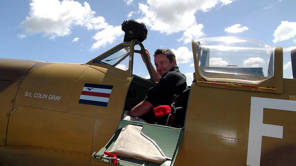
Post by corsairarm on Jan 10, 2023 13:03:20 GMT 12
I'll look in our Sunderland when we get back next Wednesday and hopefully post a photo with Daves help.
|
|
|
|
Post by davidd on Jan 10, 2023 15:35:38 GMT 12
In the meantime, a few extracts from AP 1566E-PN (Pilot's and Flight Engineer's Notes, Sunderland V : Four Twin Wasp R-1830-90B Engines) might provide some useful idea of the layout of the various trimming arrangements. In the text below, numbers in brackets refer to the various named items under discussion.
Para 14, Trimming Tabs: The elevator and rudder trimming tab controls are operated by crank handles (61) and (66) mounted in the cockpit roof.
Movement of the crank handles is in the natural sense and indicators (60) and (59) show the settings of the tabs. Two fixed trimming tabs are fitted on each aileron.
Figure No. 3 in same publication clearly shows the "Cockpit Roof" items, as well as the indicators, with all but the elevator trim indicator mounted on underside of the fore-and-aft central overhead structure mounted on aircraft centreline.
The rudder trim crank handle is mounted just aft of the (overhead) Master fuel cock levers, with centre-line of crank vertical, while the two elevator trim crank handles are mounted just in front of the rudder trim gear, but with centre-line of the two cranks (one mounted each side for attention from either pilot) being athwartships (I love that term, just the job for these nautical applications!) The indicator for the elevator trim tab is shown mounted on starboard side of the fore-and-aft central overhead structure (and it is quite possible that an identical unit was mounted on port side as well, to enable the captain to read his side more easily!)
Reference to the actual AP Figure No. 3 makes the rather detailed description masterminded by me (above) a whole lot easier to envisage.
|
|