

Post by agile on Apr 29, 2023 12:09:50 GMT 12
I'm stuck at home for the day, so a good opportunity for a long-overdue Mossie update.
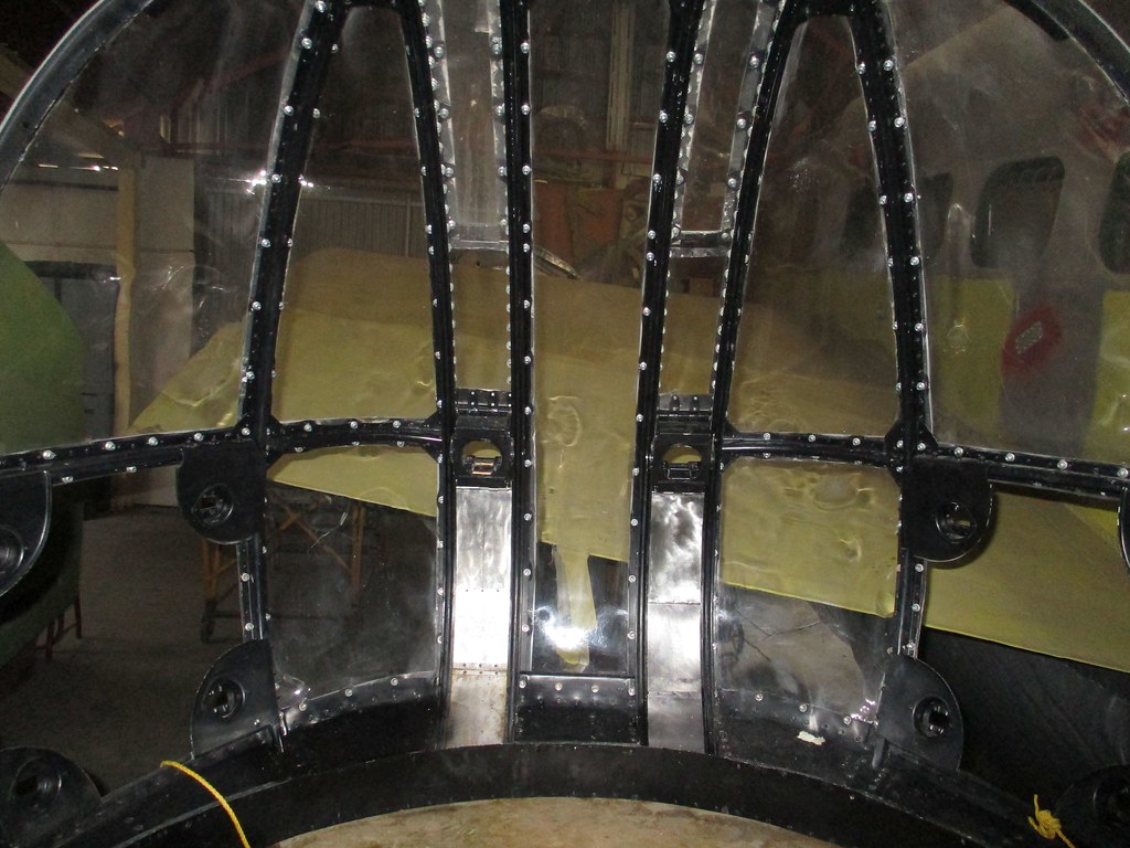
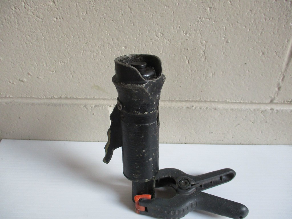
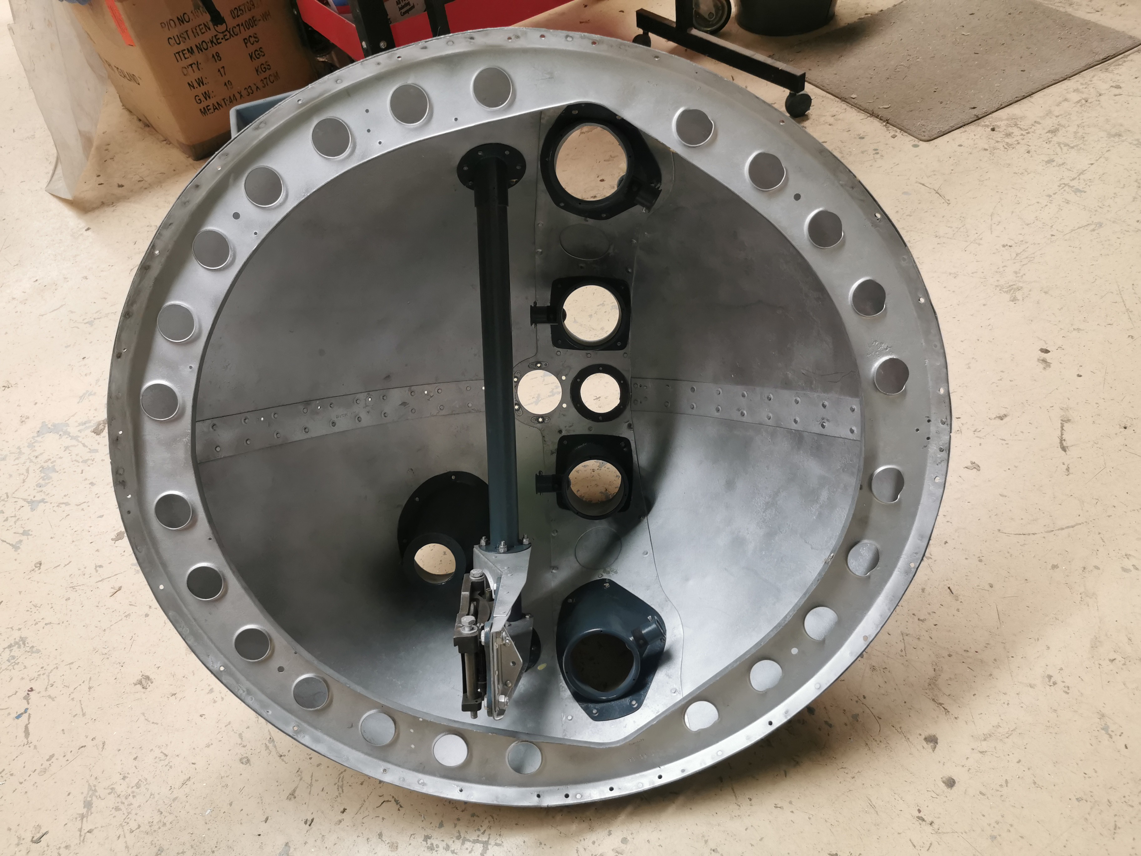
Folloiwng on from the last update, the nose cone is now back together and ready to go back on:

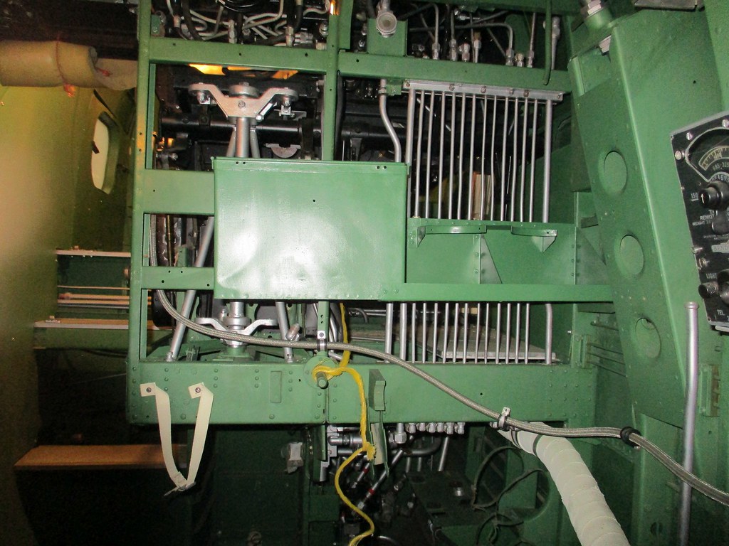
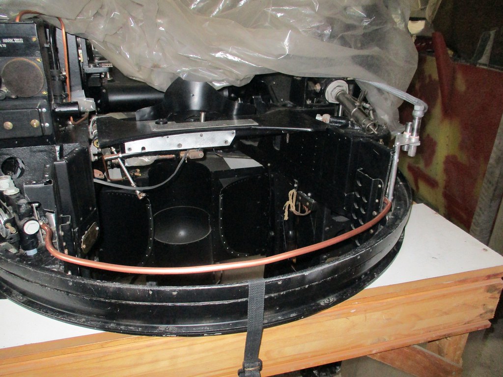
In the meantime the machine gun bay has been tidied up and painted:

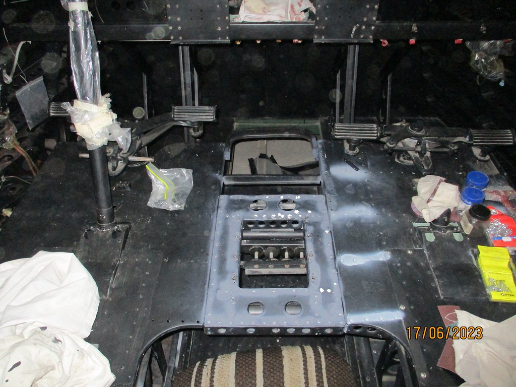
Another little job that has been on my to-do list for way too long was finishing the repairs to the cockpit floor. The cockpit floor is separated into two halves joined to each half of the fuselage shell. The joint in the middle of the floor is stiffened with a strip of 2mm ply top and bottom, and part of the top strip was cut away during the floor repairs (see page 12 of this thread way back in 2019). The strip is attached with alternating brass screws and gimp pins, which was pretty tedious, but ultimately satisfying when done:

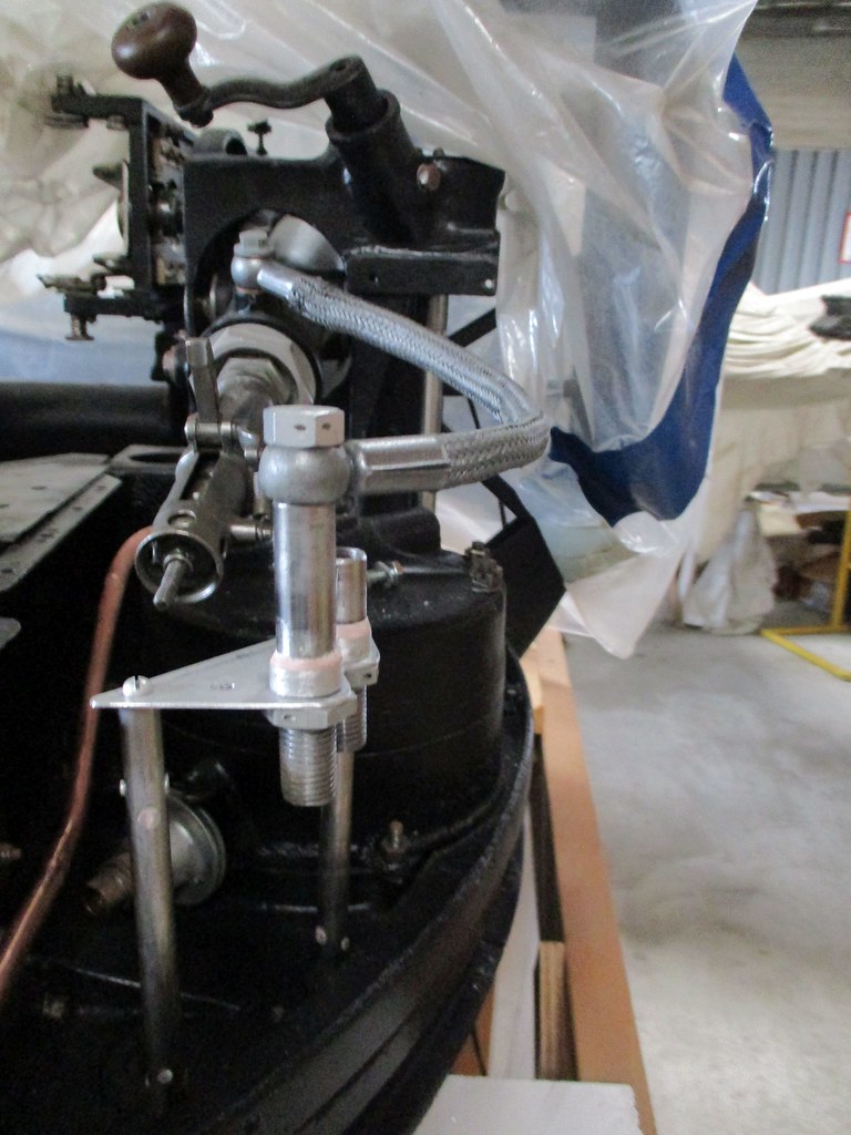
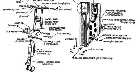
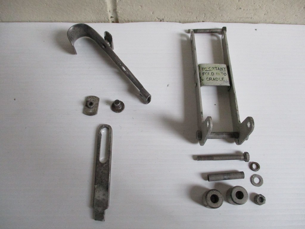
Another job that had been nagging at me for a while was the bracket for the U/V lamp 'exciter' button. The old-pattern U/V lamps use a big ballast resistor box mounted on BH2 in the cannon bay and an exciter button that had to be held down to fire up the lamps. These were replaced around the end of the war by the smaller and simpler red type which have a simple on/off switch. We had the lamps (they're relatively common for some reason, perhaps they were used on the Oxbox or Anson too). We got hold of the button from Australia and the resistor box from the UK, and the wiring loom that Angus has been patiently lacing up (mentioned by Denys above) has been modified to include the necessary cabling. Unfortunately we didn't have the bracket, or a drawing for it (just the mounts for it in the cockpit). One of Dagy's mates in the UK measured up the bracket on HJ711 at East Kirkby, which provided some of the info I needed. Then Dylan up at Avspecs kindly dredged up a loose one from their treasure store, and sent me full dimensions and pics:

Being British it's absurdly over-engineered, with tabs folded over and riveted. I'm a sheet-metal tyro, so I made a CAD drawing of the developed bracket before getting brave enough to cut metal (in metric too, don't anyone tell Dagy):

Then proceeded to the real thing (with a bit of a bending tutorial from Dagy along the way):

Last weekend we finally finished a job that has been annoying us for ages. These are the link chutes that sit under the .303 Brownings: They have a rubbing strip of felt riveted on where they contact the underside. The chutes are steel and were pretty rusty so all the felt had to come off for corrosion treatment and painting. Then it was 'simply' a case of riveting the felt back on. Unfortunately the rivets do tend to want to expand into the soft felt instead of forming over. This task involved a lot of 'swearing, volunteers for the use of' and repeated drilling on out bent rivets and manufacture of new securing strips.

In the course of tidying up the repairs to the fuselage I came across an undetected patch of rot between the cockpit door and the fuselage side panel:

So off with the skin and out with the rotten balsa:

New balsa and feathered edges:

A matching patch:

Glue, screws and clamps:

Every time I think this will be the last fuselage repair, but this one really might. With the fuselage woodwork nearing completion, it's time to think about fabric. The repaired area of fuselage has been gradually red-doped (hiding the fruits of our labours):

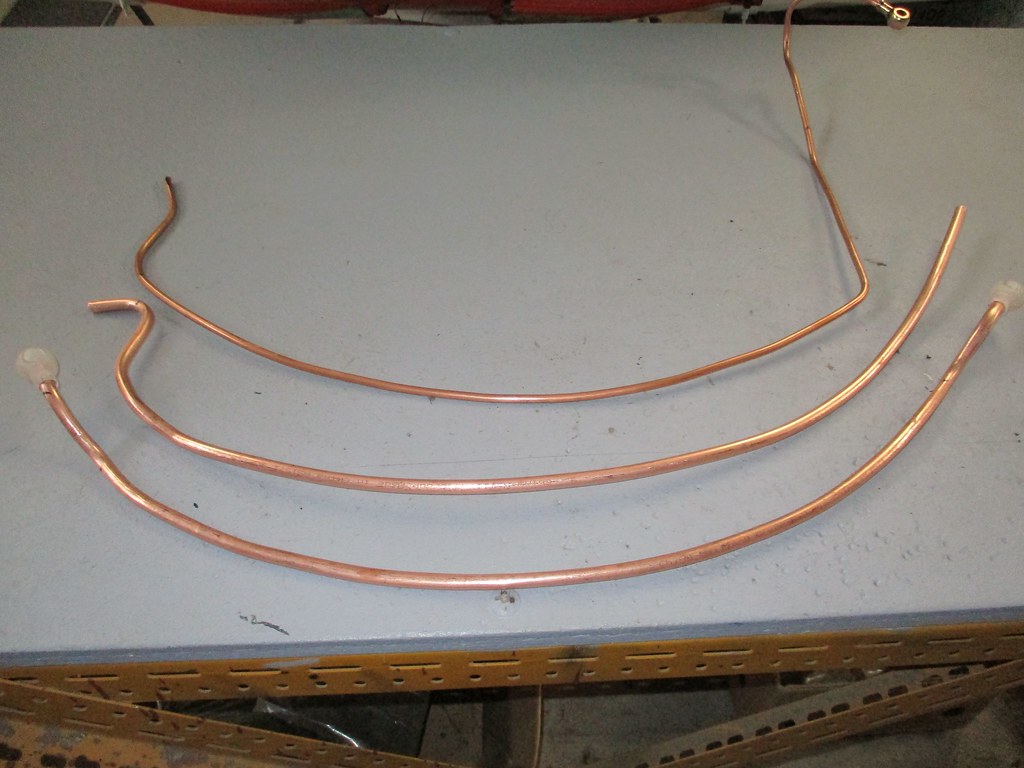
I've started putting in the sealing strips of bias cut fabric that cover the exposed end grains of the structure. Here's the one around the nose:

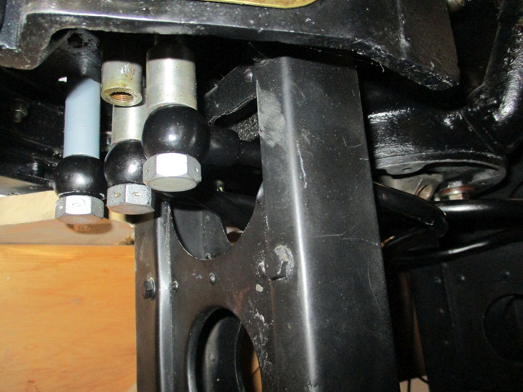
HF aerial mast and long range tank filler openings:

Machine guns bay lower panel:

And the opening for the navigator's drift recorder in the side of the cockpit:

Even the openings inside the cockpit are covered. Here's the hole for the HF trailing aerial in the cockpit floor:

We won't be fitting a trailing aerial, so I made a paxoline cover plate to go over the hole, based on the only drawing I could find:


Dagy has procured me some thin bendy paxoline to make the outer cover, which will be a bit trickier.
I'm starting to think about how we can do the main fabric cover while the fuselage is cradled in its jig (especially the one under bulk head 2, where we may actually have to do a bit of minor repair work). Current thinking is that we leave the wing centre section in place and propped up while the lower fabric panels are done. If the repaired fuselage isn't strong enough to be supported in this manner, we'll have a problem ever getting the aircraft on its legs, but we're quietly confident in our work. Oh for a rotating jig though.
George and his young apprentices Reid and Oscar have been having fun reassembling the first of the ailerons. There are some very tight angles to rivet into, but at least he's smiling right:


The final skin for the other aileron went back to Dagy's for corrosion treatment last week. He sent me these pics of a another slightly agricultural battle damage repair - there was a war on I guess:


Unfortunately this skin is corroded beyond salvage. We're crossing our fingers that out spare aileron, which is also pretty buggered is (a) from the same side and (b) jig drilled.
If you look back a few pages you'll see a 3d printed template for the elevator cable pulley bracket. Unfortunately we had to give up trying to get it cast, so Dagy has fabricated one from ally plate. He texted me some pics while I was writing this novel-length update - looks pretty good to me:


In investigating the wing structure we've started realising the enormity of the task in terms of materials. The spar webs are attached to the booms with #14x 2 1/2" (ie massive) woodscrews. These are going to be seriously spendy, so if you have any loose change, well, see our Givealittle link here or in my signature.
Anyway, hope this wasn't TMI - thanks for reading!
Cheers
A
Folloiwng on from the last update, the nose cone is now back together and ready to go back on:
In the meantime the machine gun bay has been tidied up and painted:
Another little job that has been on my to-do list for way too long was finishing the repairs to the cockpit floor. The cockpit floor is separated into two halves joined to each half of the fuselage shell. The joint in the middle of the floor is stiffened with a strip of 2mm ply top and bottom, and part of the top strip was cut away during the floor repairs (see page 12 of this thread way back in 2019). The strip is attached with alternating brass screws and gimp pins, which was pretty tedious, but ultimately satisfying when done:
Another job that had been nagging at me for a while was the bracket for the U/V lamp 'exciter' button. The old-pattern U/V lamps use a big ballast resistor box mounted on BH2 in the cannon bay and an exciter button that had to be held down to fire up the lamps. These were replaced around the end of the war by the smaller and simpler red type which have a simple on/off switch. We had the lamps (they're relatively common for some reason, perhaps they were used on the Oxbox or Anson too). We got hold of the button from Australia and the resistor box from the UK, and the wiring loom that Angus has been patiently lacing up (mentioned by Denys above) has been modified to include the necessary cabling. Unfortunately we didn't have the bracket, or a drawing for it (just the mounts for it in the cockpit). One of Dagy's mates in the UK measured up the bracket on HJ711 at East Kirkby, which provided some of the info I needed. Then Dylan up at Avspecs kindly dredged up a loose one from their treasure store, and sent me full dimensions and pics:
Being British it's absurdly over-engineered, with tabs folded over and riveted. I'm a sheet-metal tyro, so I made a CAD drawing of the developed bracket before getting brave enough to cut metal (in metric too, don't anyone tell Dagy):
Then proceeded to the real thing (with a bit of a bending tutorial from Dagy along the way):
Last weekend we finally finished a job that has been annoying us for ages. These are the link chutes that sit under the .303 Brownings: They have a rubbing strip of felt riveted on where they contact the underside. The chutes are steel and were pretty rusty so all the felt had to come off for corrosion treatment and painting. Then it was 'simply' a case of riveting the felt back on. Unfortunately the rivets do tend to want to expand into the soft felt instead of forming over. This task involved a lot of 'swearing, volunteers for the use of' and repeated drilling on out bent rivets and manufacture of new securing strips.
In the course of tidying up the repairs to the fuselage I came across an undetected patch of rot between the cockpit door and the fuselage side panel:
So off with the skin and out with the rotten balsa:
New balsa and feathered edges:
A matching patch:
Glue, screws and clamps:
Every time I think this will be the last fuselage repair, but this one really might. With the fuselage woodwork nearing completion, it's time to think about fabric. The repaired area of fuselage has been gradually red-doped (hiding the fruits of our labours):
I've started putting in the sealing strips of bias cut fabric that cover the exposed end grains of the structure. Here's the one around the nose:
HF aerial mast and long range tank filler openings:
Machine guns bay lower panel:
And the opening for the navigator's drift recorder in the side of the cockpit:
Even the openings inside the cockpit are covered. Here's the hole for the HF trailing aerial in the cockpit floor:
We won't be fitting a trailing aerial, so I made a paxoline cover plate to go over the hole, based on the only drawing I could find:
Dagy has procured me some thin bendy paxoline to make the outer cover, which will be a bit trickier.
I'm starting to think about how we can do the main fabric cover while the fuselage is cradled in its jig (especially the one under bulk head 2, where we may actually have to do a bit of minor repair work). Current thinking is that we leave the wing centre section in place and propped up while the lower fabric panels are done. If the repaired fuselage isn't strong enough to be supported in this manner, we'll have a problem ever getting the aircraft on its legs, but we're quietly confident in our work. Oh for a rotating jig though.
George and his young apprentices Reid and Oscar have been having fun reassembling the first of the ailerons. There are some very tight angles to rivet into, but at least he's smiling right:
The final skin for the other aileron went back to Dagy's for corrosion treatment last week. He sent me these pics of a another slightly agricultural battle damage repair - there was a war on I guess:
Unfortunately this skin is corroded beyond salvage. We're crossing our fingers that out spare aileron, which is also pretty buggered is (a) from the same side and (b) jig drilled.
If you look back a few pages you'll see a 3d printed template for the elevator cable pulley bracket. Unfortunately we had to give up trying to get it cast, so Dagy has fabricated one from ally plate. He texted me some pics while I was writing this novel-length update - looks pretty good to me:
In investigating the wing structure we've started realising the enormity of the task in terms of materials. The spar webs are attached to the booms with #14x 2 1/2" (ie massive) woodscrews. These are going to be seriously spendy, so if you have any loose change, well, see our Givealittle link here or in my signature.
Anyway, hope this wasn't TMI - thanks for reading!
Cheers
A