|
|
Post by general on Apr 6, 2016 21:29:56 GMT 12
Gentlemen. It's time for a build WIP. Another commission for Kevin, in Rotorua. He has the Vampire FB 5/52 or the Canberra. I feel he was leaning heavily towards the B (I) 8. The Airfix Canberra is very solid. No chance of warping with this industrial-weight plastic. Closing the bomb bay leaves out almost two whole sprues of parts. Natch, I pored over every posted build I could find. Nice site on IPMS UK - Canberra SIG. First and foremost, the weight issue to avoid a tail-sitter. Plans call for 100gm. Instead of trying to cram lead into every nook and cranny with copious epoxy I employed a technique I've developed for one-off castings. I use crayon wax. It's a pain to try melting (as mentioned on pics) it out of the mold. With some extra thought and preparation a saw cut through the centre of the plaster solves that challenge. Conformal weights almost eliminate wasted space from using round shot or fishing weights. The 'trench fairy' had the usual field day. Patience with melted sprue and tape, and I'm ready to re-scribe much thinner lines. Both the engine intakes and exhausts demand thinning of the apertures. Instead of gnashing teeth trying to eliminate seams on the intakes I revised the Airfix idea. Removing the rear 'rib' that secures the compressor faces I could now attend any seam-filling and install the engine parts afterward. I'll let the pics tell the rest, then answer the inevitable "What's that mean . . ?" 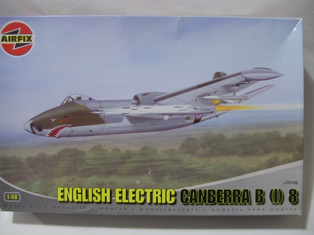 1 00 Airfix B I 8 1 00 Airfix B I 8 by scap.design, on Flickr 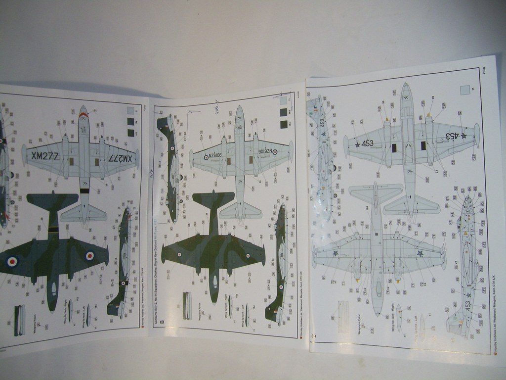 1 01 Airfix Kit Plans 1 01 Airfix Kit Plans by scap.design, on Flickr 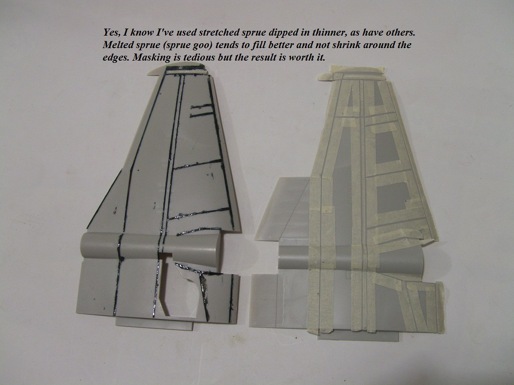 1 Wings Tape_Sprue Lines 1 Wings Tape_Sprue Lines by scap.design, on Flickr 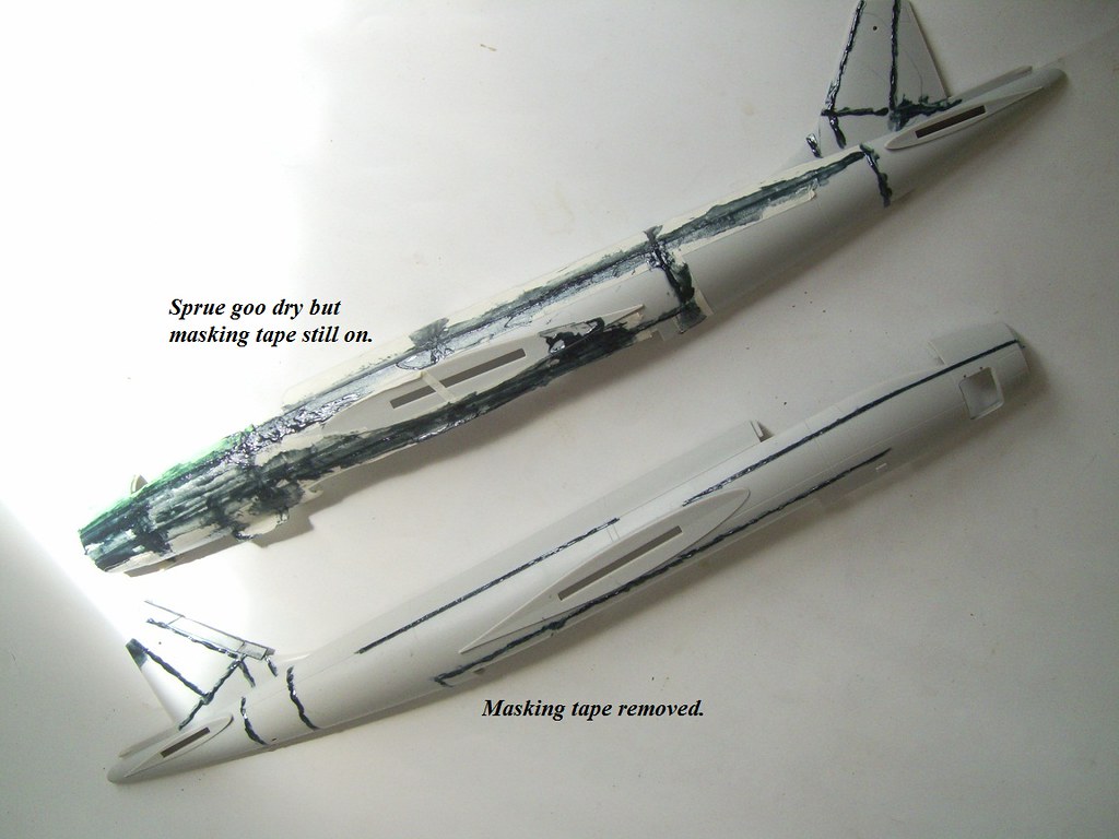 1 Fuz Sprue Lines 01 1 Fuz Sprue Lines 01 by scap.design, on Flickr 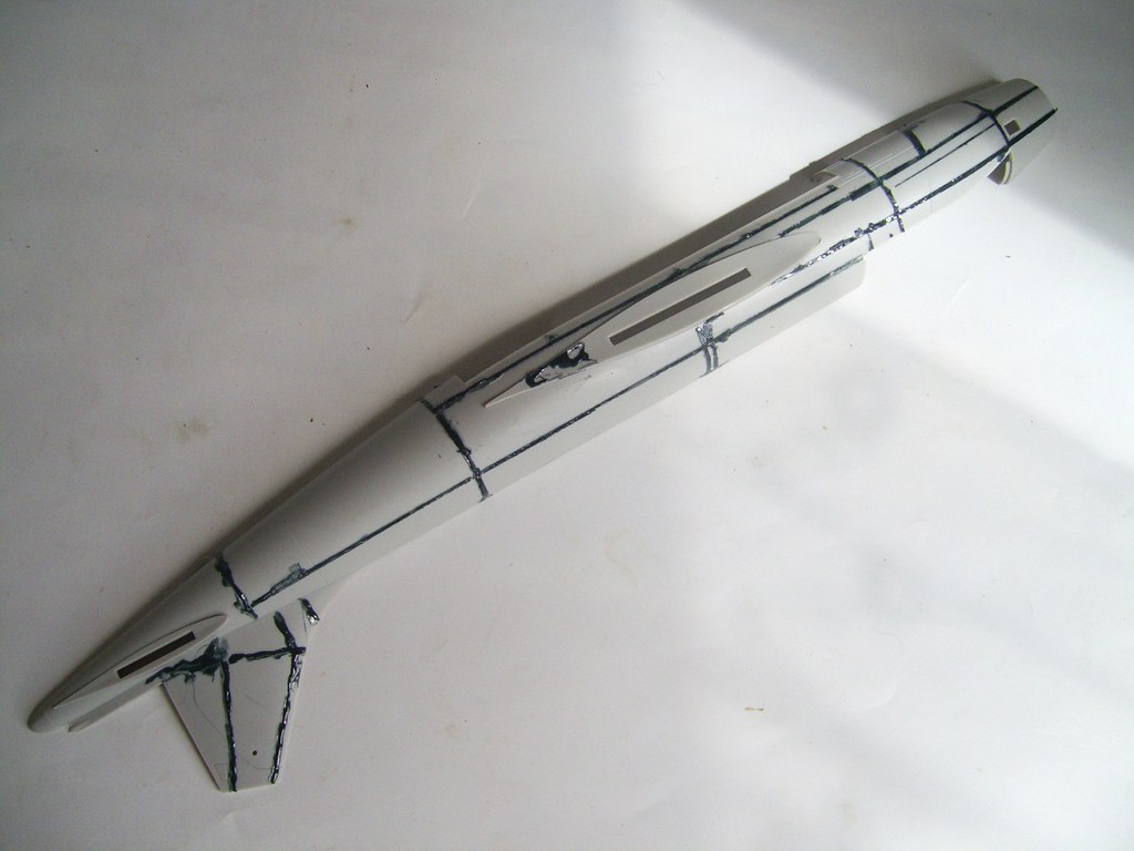 1 Fuz Sprue Lines 02 1 Fuz Sprue Lines 02 by scap.design, on Flickr 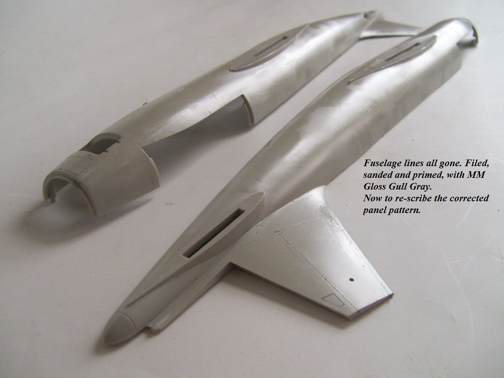 1 Fuz Primed 02 1 Fuz Primed 02 by scap.design, on Flickr This will kick things off. More to post. Regards Rossky |
|
|
|
Post by ZacYates on Apr 7, 2016 9:55:11 GMT 12
I'm excited! Great start.
|
|
|
|
Post by camtech on Apr 7, 2016 10:09:02 GMT 12
Looking good!
|
|
|
|
Post by saratoga on Apr 7, 2016 17:40:03 GMT 12
Looks good, shame they did so many trenches on what was a smooth airframe.
Have you altered the fin fillet? ,i think it is too long and shallow curve.Should be easy enough to sand to a better profile.
|
|
|
|
Post by general on Apr 7, 2016 22:39:01 GMT 12
I've seen four or five online builds, even the UK IPMS Sig (a must-see before starting the Airfix). One of the first items of surgery across the board is the fin fillet. However, not one peep about a possibly narrow fin profile. In the course of research I measured up the fuselage against a couple side views, scaled to 1/48th, and the fin showed up short along the L/E about 2-2 1/2 mm. Hmmm . . . this wasn't in the movie . . . Filed a flat edge along the L/E and added scrap styrene, faired in with putty and re-shaped the contour. That put the rudder about 1mm short, but I re-profiled that according to build notes anyway. Simple fix to add a stick of sprue, filed flat on one side for a datum surface. Then shaped and gaps filled accordingly. Now I could re-shape the fillet radius. Meanwhile, what I did for the nose weight: Found some old crayons in a drawer, long time back. Lightbulb moment was, "I could melt these for cavities, make excellent mold masters". 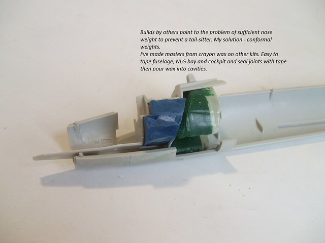 2_01 Wax Mould 2_01 Wax Mould by scap.design, on Flickr The bugbear of this kit is the large moment arm aft, instructions ask for 100gm over the NLG bay. Builders had dramas stuffing lead or bolts inconspicuously. I believe in 'economic use of time and resources'. Figured out where the hidden spaces were and set to casting. Overdid it a little, aft of cockpit. Figured that would be the most effective space with the bomb-bay shut. Once cast, that hunk of lead must have been closer to 300-350gm. I've since sawed off the lower 'arms' to use either side of the NLG bay. Added to the remainder of the contour weights it pegs out a smidge over 100gm. 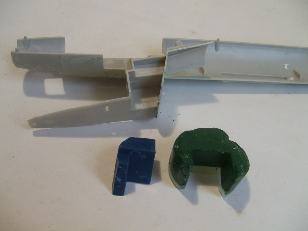 2_02 Wax Mould 2_02 Wax Mould by scap.design, on Flickr This is the plaster mold for the big chunk aft of cockpit. You can see the fracture line. Thought I'd cast it one solid block, then remove sprues for the pour holes and heat it in the oven to melt the wax. Stubborn cuss merely expanded rather than flowed, and split the plaster. 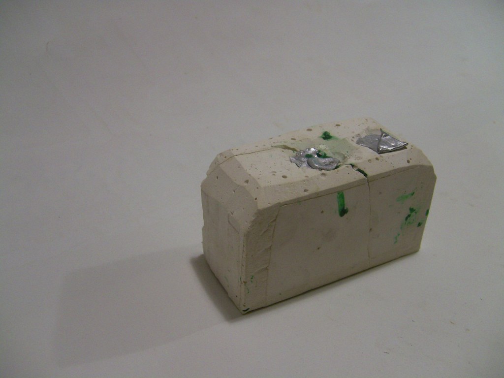 2_03 Plaster Casting 2_03 Plaster Casting by scap.design, on Flickr Little PITA wasn't going to defeat me. At least I could now remove most of the wax (heating with a flame to move it). White-glued it together, clamped and poured lead. I scrounge old wheel balance and fishing weights. My 'crucible' is a stainless steel cap from something, heated on the stove-top and holds about 600-700gm of lead. It's the coolest thing pouring hot lead. Turned out an ugly sucker, with all that residual wax clinging, but we only need weight, not aesthetics. 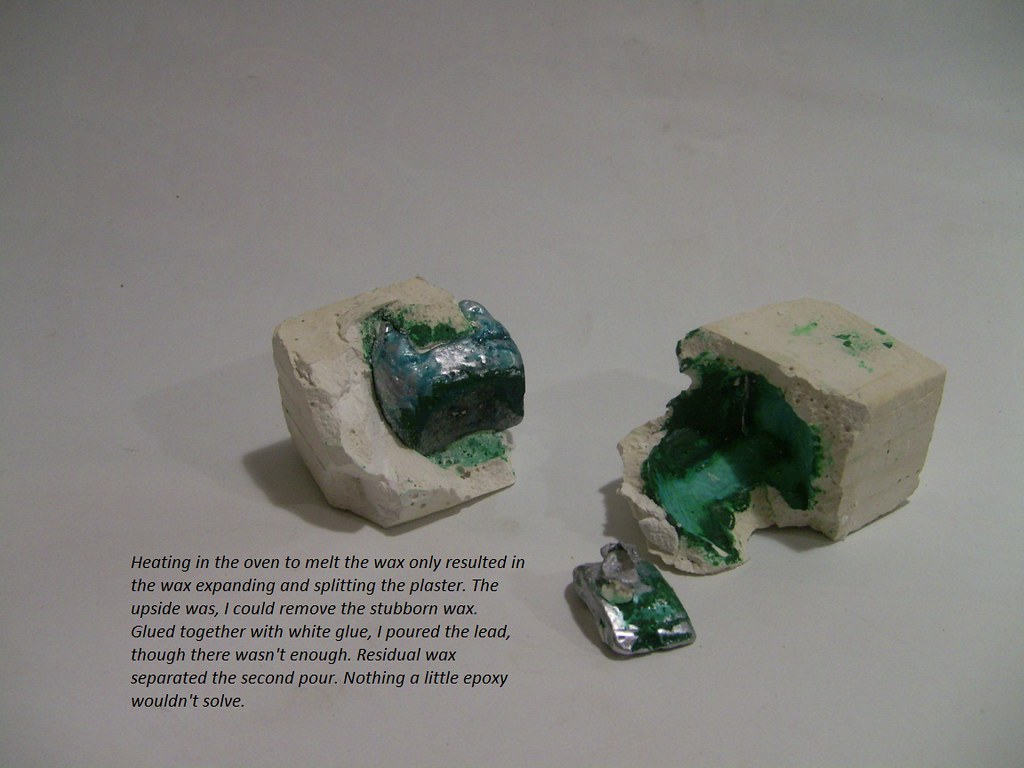 2_05 Casting Weight 2_05 Casting Weight by scap.design, on Flickr Experience builds confidence. Onto the cockpit side cavity. I built a collapsible casting box out of CD cases a ways back. Designed to do 1/32nd SBD and 1/24th P-51D canopy masters. Simple task to blank off a suitable volume. Different strategy here. Mounted the wax master with pour stubs horizontal, and Blu-tac'd to the box wall. Plaster up to the mid-point of the stubs and set. Removed this half-casting, trimmed the surface flat and tidied up around the stubs. Back into the box and poured the second plaster. This creates a distinct line between the halves. Pulled out the stubs then put a thin saw blade through this line, around the block and through the wax. 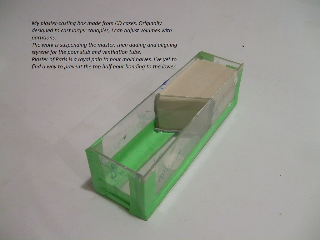 2_04 Plaster Casting 2_04 Plaster Casting by scap.design, on Flickr Heated and cleaned out the wax - far cleaner job this time - and replaced the datum posts (old Qtip shafts). But we ain't done quite yet. An uneven saw cut would pose problems with gaps. Smeared the mating face of one plaster half with epoxy, laid down a clingfilm barrier then put halves together. Once set, off with clingfilm and we have a sealed mold. 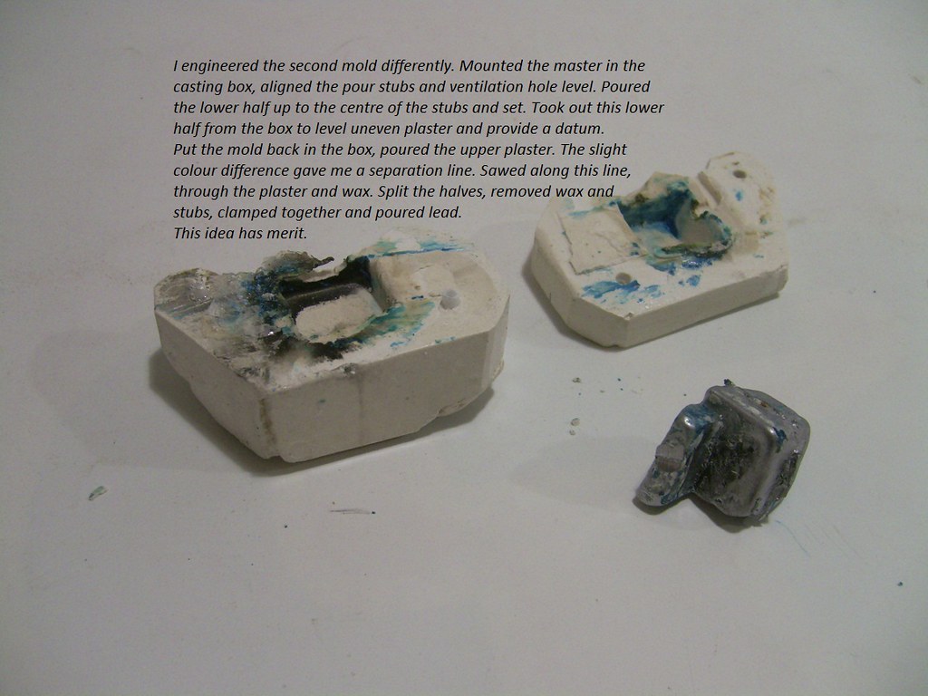 2_06 Casting Weight 2_06 Casting Weight by scap.design, on Flickr 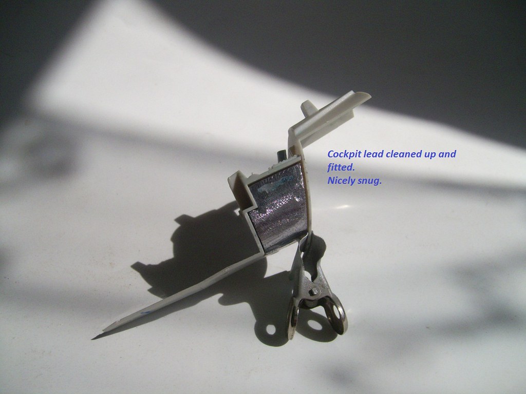 2_07 Cast Weight 2_07 Cast Weight by scap.design, on Flickr Put things together for weight and balance checks. Want to see a comparison with the Skyhawk? Taped up the Esci fuz out of curiosity. 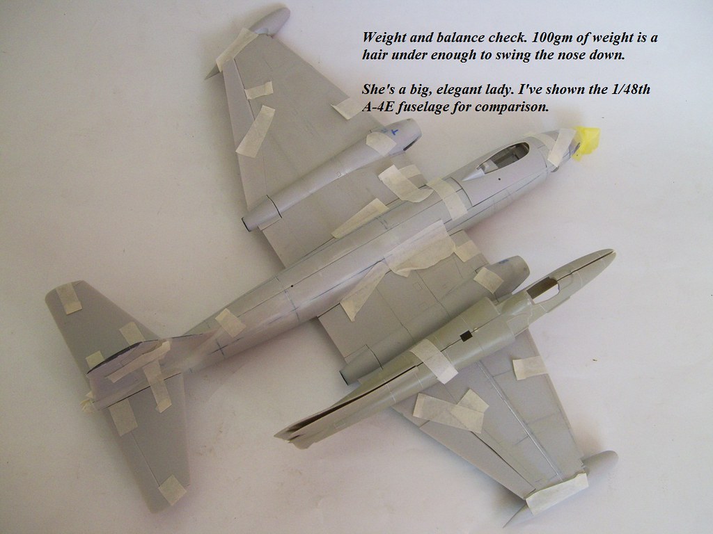 3 Balance_and_Weight Check B 3 Balance_and_Weight Check B by scap.design, on Flickr That'll do, for now. On to engines next . . . Regards ybiC |
|
|
|
Post by ZacYates on Apr 8, 2016 9:58:32 GMT 12
A brilliant idea. You could probably sell these weights too, if you perfect the casting process!
|
|
|
|
Post by saratoga on Apr 8, 2016 16:17:31 GMT 12
For your mold,certainly for one offs and using the wax masters,have a flow channel(seperate from the pour channel) for the wax to flow out as the lead melts and replaces it in the cavity.
Also ensure your plaster is very well cured as that will split or explode if it has too high a moisture content. AKA lost wax casting,a technique often used for one off jewellery making.
Otherwise a cunning solution!.
|
|
|
|
Post by general on Apr 9, 2016 16:49:30 GMT 12
Cheers, Saratoga. Step ahead of ya, there. Been Watching and testing the process for so many years, if I could build a workshop a forge and smelter is mandatory. Here's my basic attack plan: 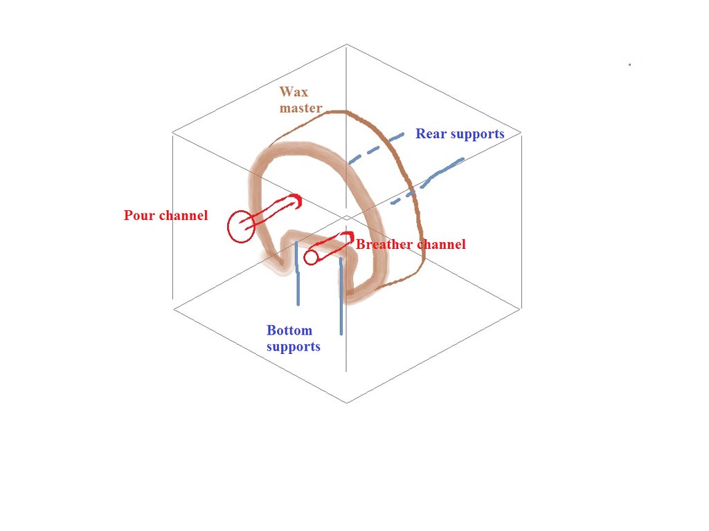 Mold Diag. Mold Diag. by scap.design, on Flickr This is the for'd inst bay recesses: 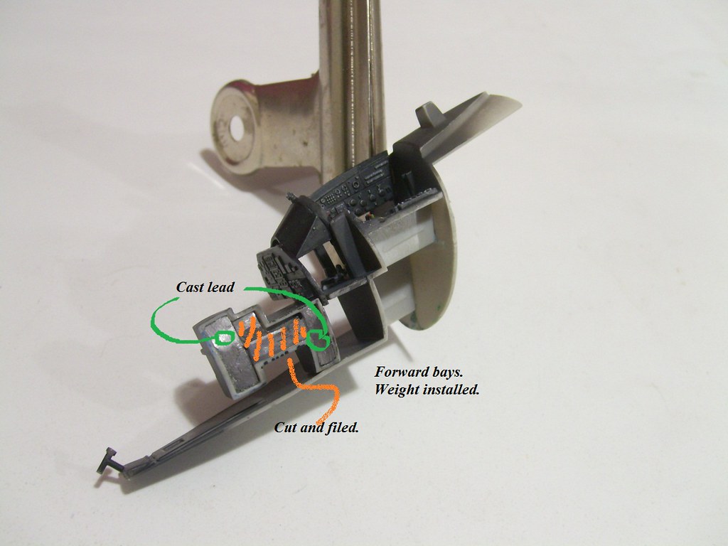 Forward Weight Forward Weight by scap.design, on Flickr So, I cut down the big chunk, using only the lower extensions that fit either side of the NLG bay. For giggles, and a little insurance, I put together a few strips of type-setters' lead (have a bunch from a newspaper production room years ago) to fit under the nose floor. We're probably pushing 110-115 gm: 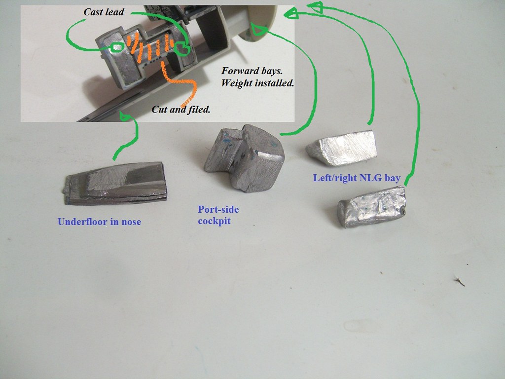 Total Weight Total Weight by scap.design, on Flickr Cockpit OOB. Shot a black-grey mix, dry-brush of light tan and white. Put the hairy stick here and there with various colours. It's enough to pick out colours when all's buttoned up. 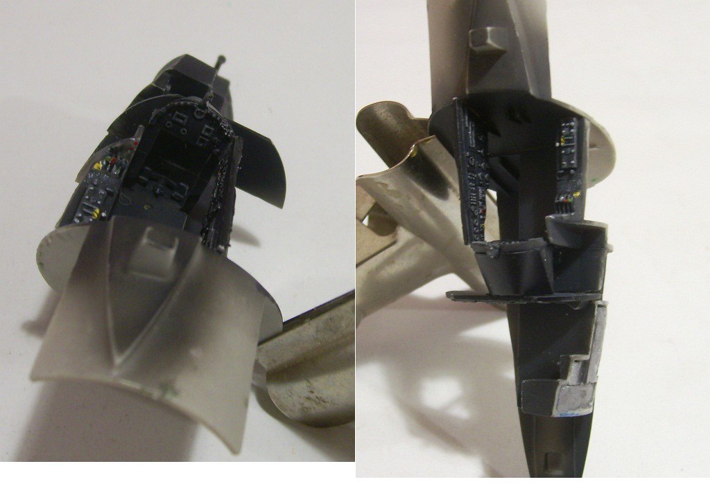 Cockpit Paint Cockpit Paint by scap.design, on Flickr Used the Eduard seatbelts for the B. 20. (Also a good set for the Fly kit of the BAC 167 Blunty, should anybody be looking). Here's the Nav seat installed. Merely an academic exercise, I also added the etch seat pan side parts. Can hardly see it through the pilot's office. 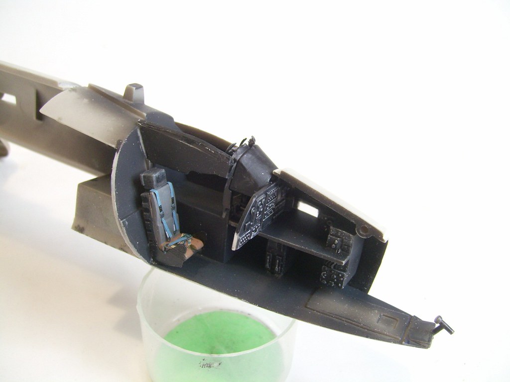 Nav Pit Nav Pit by scap.design, on Flickr We're rocking along now. Next up, minor fubar with the nose glass . . . Regards |
|
|
|
Post by general on Apr 13, 2016 15:08:37 GMT 12
Alrighty then. These should be enough to keep her nose down. Forward Weight by scap.design, on Flickr Total Weight by scap.design, on Flickr Mentioned this in o/p so I'd better explain. You can probably see the thicker vanes on the engine face. Airfix molded the ducting and vanes in one. Also, I've read notes saying there are either two or three of these "ducts", depending on engine version. Threw a coin and settled on three. Meanwhile, construction would have you fit the engine face between the nacelle halves. Sod off, I say, that'll make seam-fixing a PITA. Instead, I chopped off the rear mounting 'rib', and shaved down the front one. Now I could attend seams without interference and mount the engine part later. Thinning the rib left a gap between the nacelle and engine face. Wrapped 0.030" strip and sanded thin. 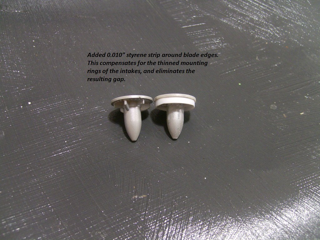 Intake Vanes Mod2 Intake Vanes Mod2 by scap.design, on Flickr 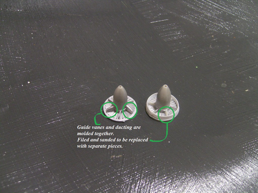 Intake Vanes Mod Intake Vanes Mod by scap.design, on Flickr The nacelle halves have no positive location. "Don't tell me, it's Airfix!" Carefully aligned holes, drilled and pinned with 0.50mm copper. Now able to sand the chunky nacelle lip to scale oontour, and fix inside seams. 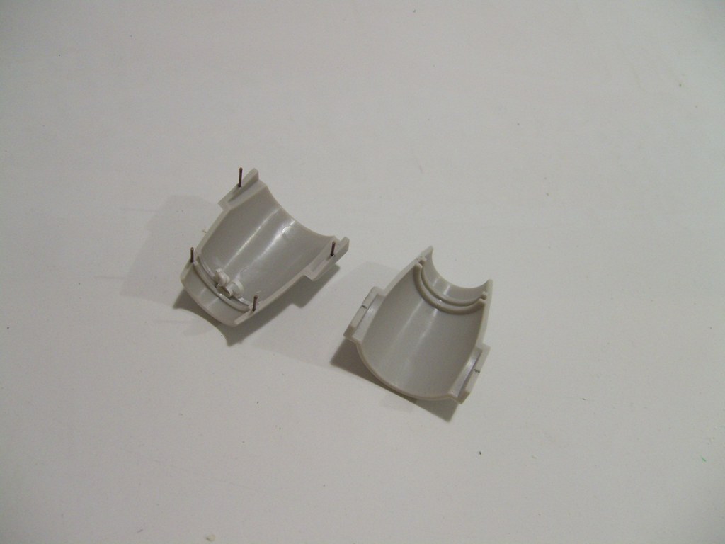 3_01 Intake Pinned 3_01 Intake Pinned by scap.design, on Flickr 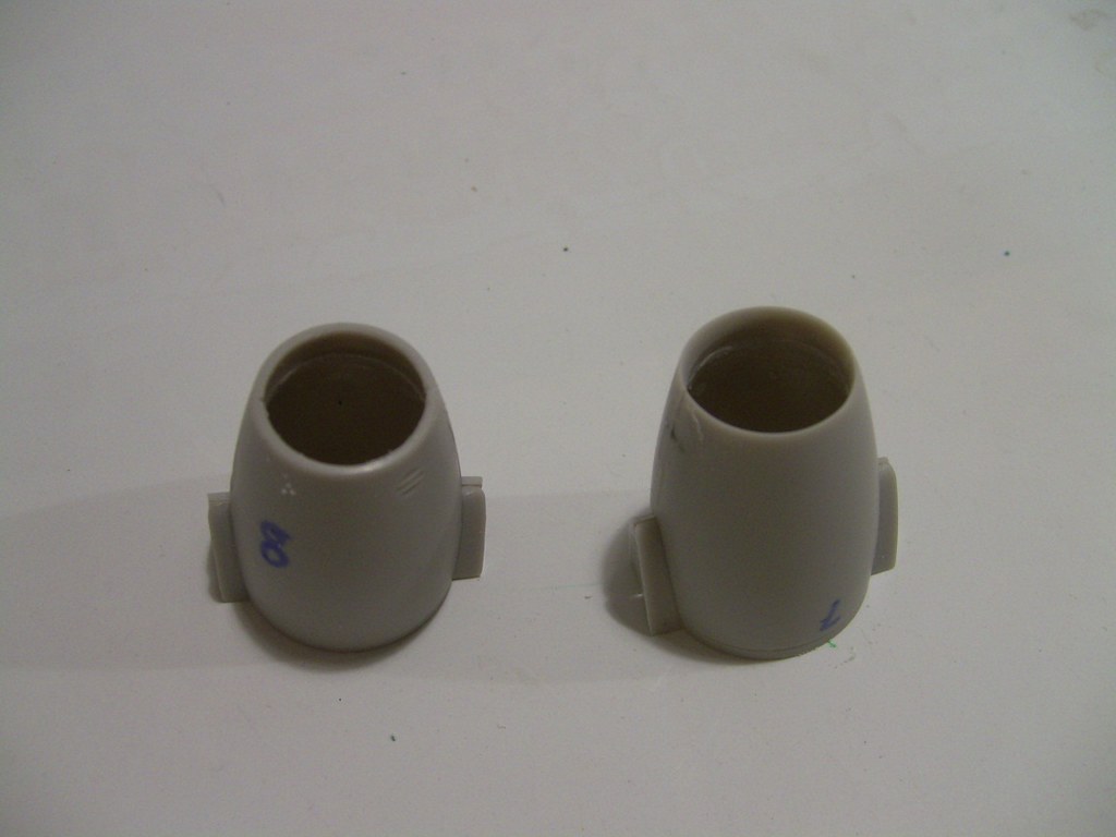 3_02 Intake Thinned 3_02 Intake Thinned by scap.design, on Flickr 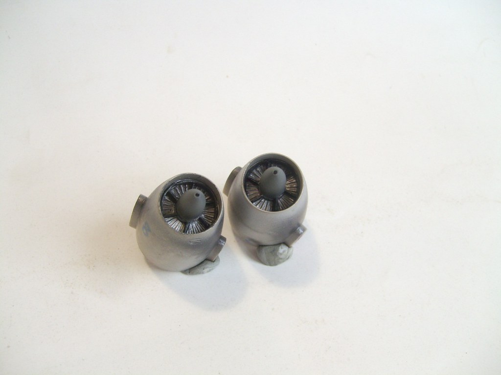 Engine Front Installed Engine Front Installed by scap.design, on Flickr Now added ducting, with shaped sprue struts. I carefully filed the ends, test-fitting until they snug-fit. Once located in line with the vanes it took a smear of CA to secure them 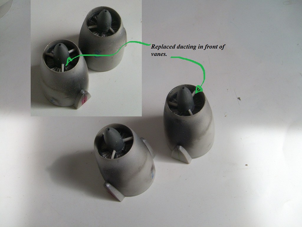 Engine Front Engine Front by scap.design, on Flickr Meanwhile, something I did to the hot end. 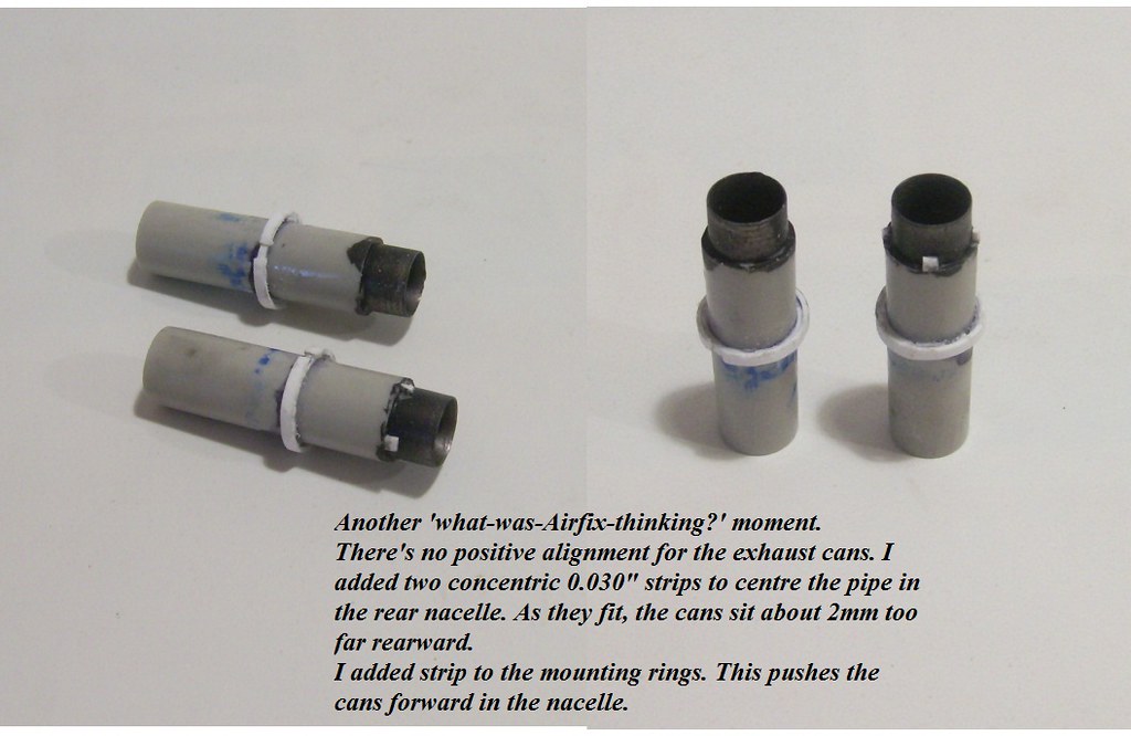 Ex Cans Mods Ex Cans Mods by scap.design, on Flickr Regards |
|
|
|
Post by general on Apr 22, 2016 21:12:16 GMT 12
Pardon the delay. I know, I know, you’re all waiting for the paint bay. Patience isn’t a virtue of many kit-bashers, is it? So, this is what the exhausts look like. 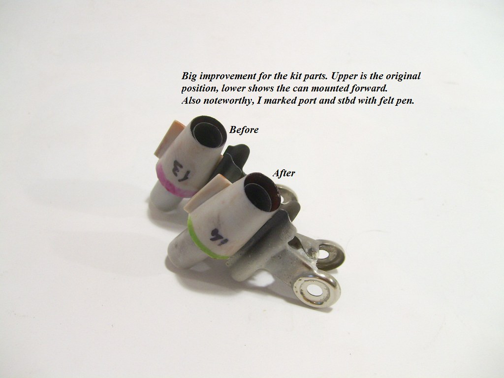 Ex Cans End Ex Cans End by scap.design, on Flickr I was a little ambitious/optimistic filling the incorrect window trenches , in the nose. Sodding sprue goo scarred the clear plastic. Whoopsie. Time to employ my usual fix, the tricky task of drilling/filing out the window and rebating some clear inserts. I brush-painted the interior grey/black, rather than the normal way of spraying the interior colour under the external. A better effect, when viewed through the clear. 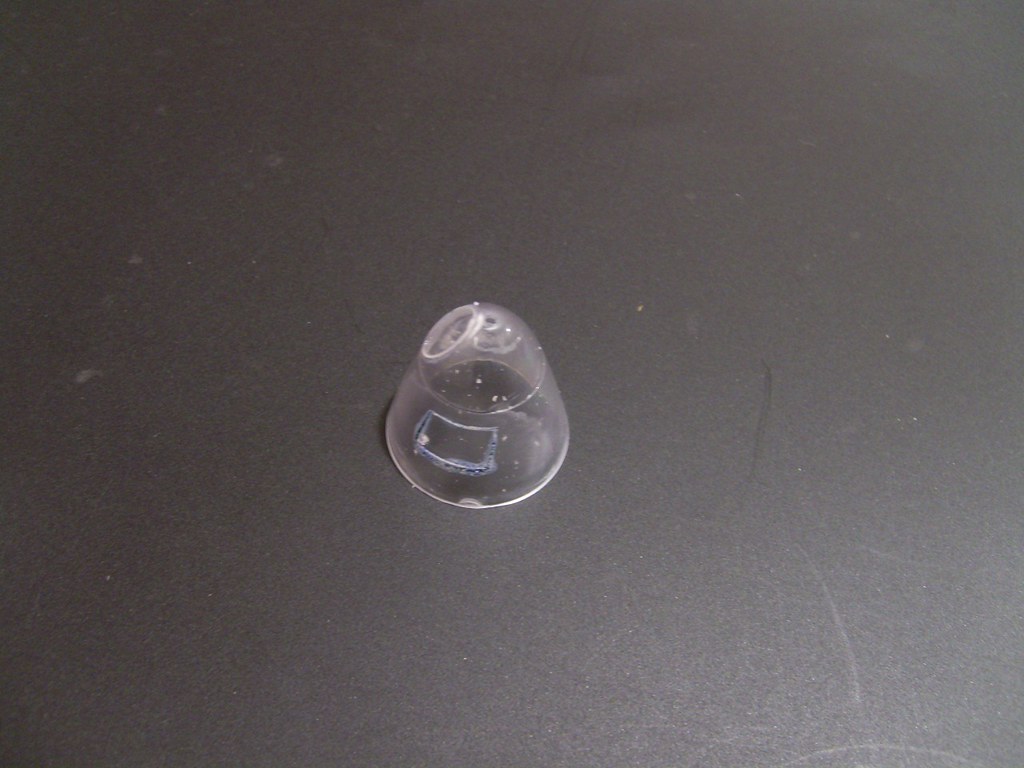 Front Glass Front Glass by scap.design, on Flickr 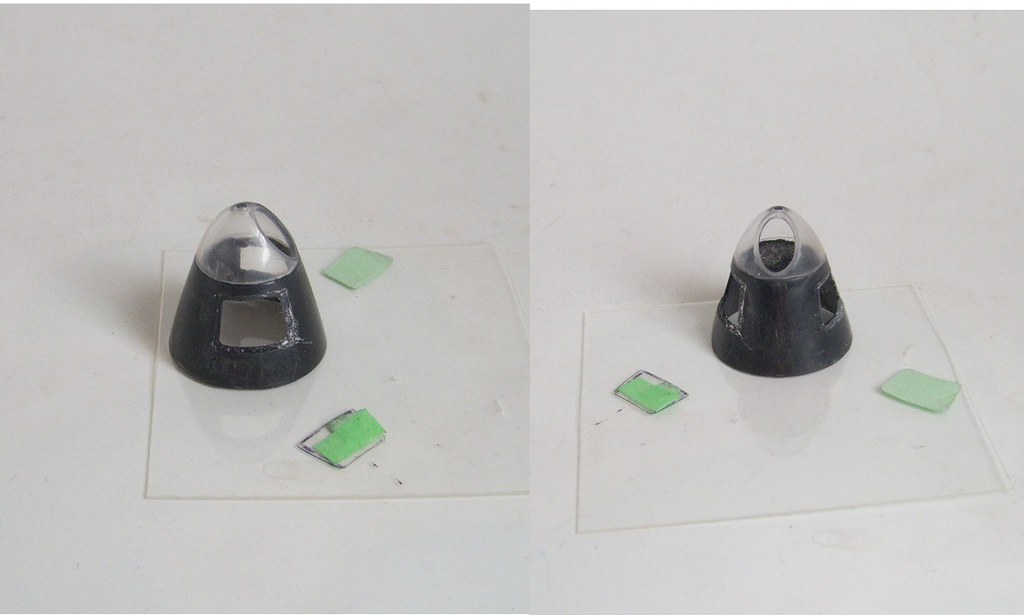 Glass Mods Glass Mods by scap.design, on Flickr Eduard PE tarted up the pilot’s seat. The good thing about PE is it gave some detail to the blank top of the kit’s seat. 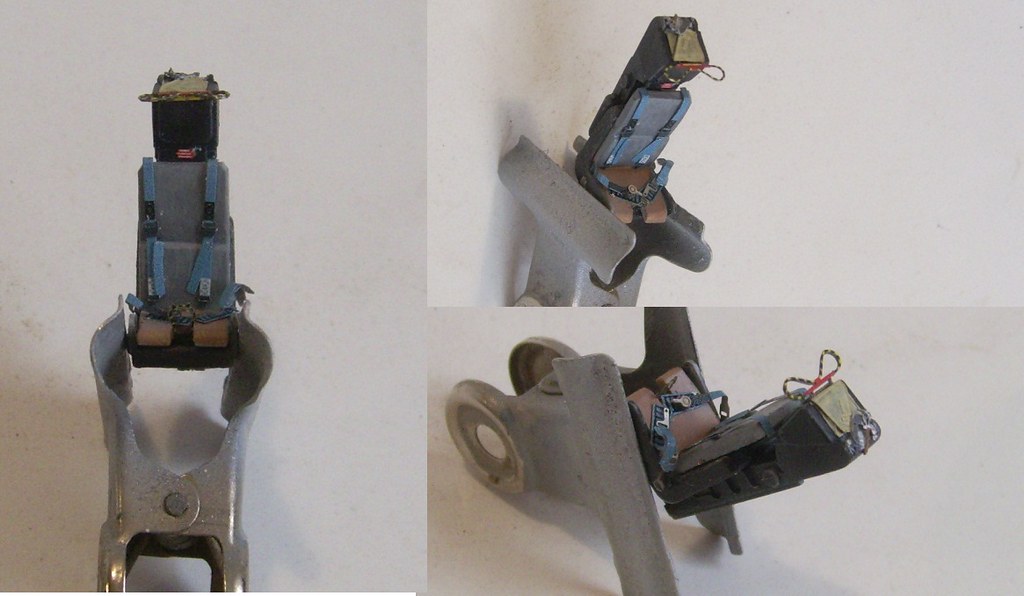 Pilot Seat Pilot Seat by scap.design, on Flickr Here’s a look at the mods to the elevator profile. Filed on top, original in blue. The kit has a fillet full-length of the hori-stab, when the elevator sits flush with the fuselage. I removed the fillet rear of the hori-stab, and the black styrene extension fills the gap. 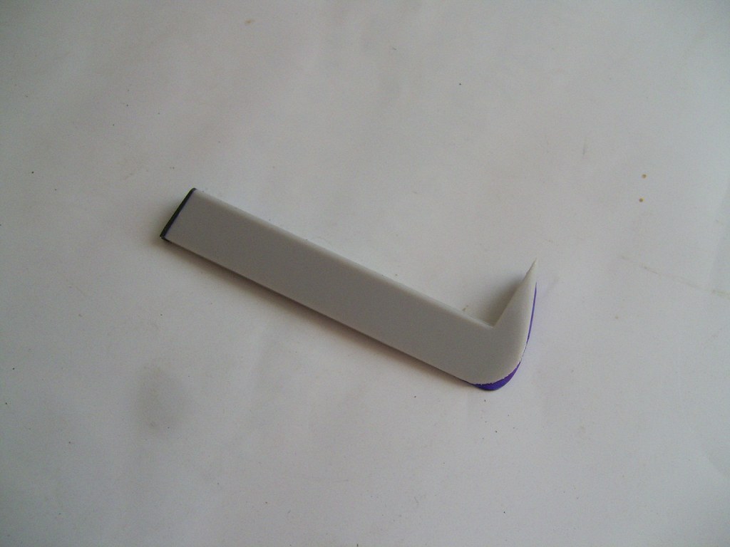 5_01 Elevators 5_01 Elevators by scap.design, on Flickr Since Airfix skimped on nose details, with a weird pole the only thing sticking up behind the nose glazing, I scratched something from styrene/litho based on pics of a B (I) 8 bombsight. Might be a bit big. 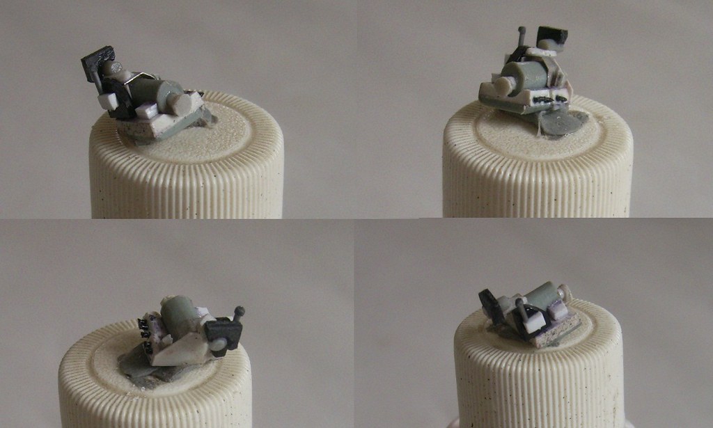 4_07 Bombsight 4_07 Bombsight by scap.design, on Flickr You'll be happy to know I've started painting, by the way . . . Regards |
|
|
|
Post by general on May 7, 2016 15:04:04 GMT 12
Gentlemen. This has been rather a protracted absence, hasn't it? Much of the distraction has, to no surprise, been fill/sand/repeat. Duelling with ghost seams, scribing scars and untidy panel lines is my Sisyphean task. 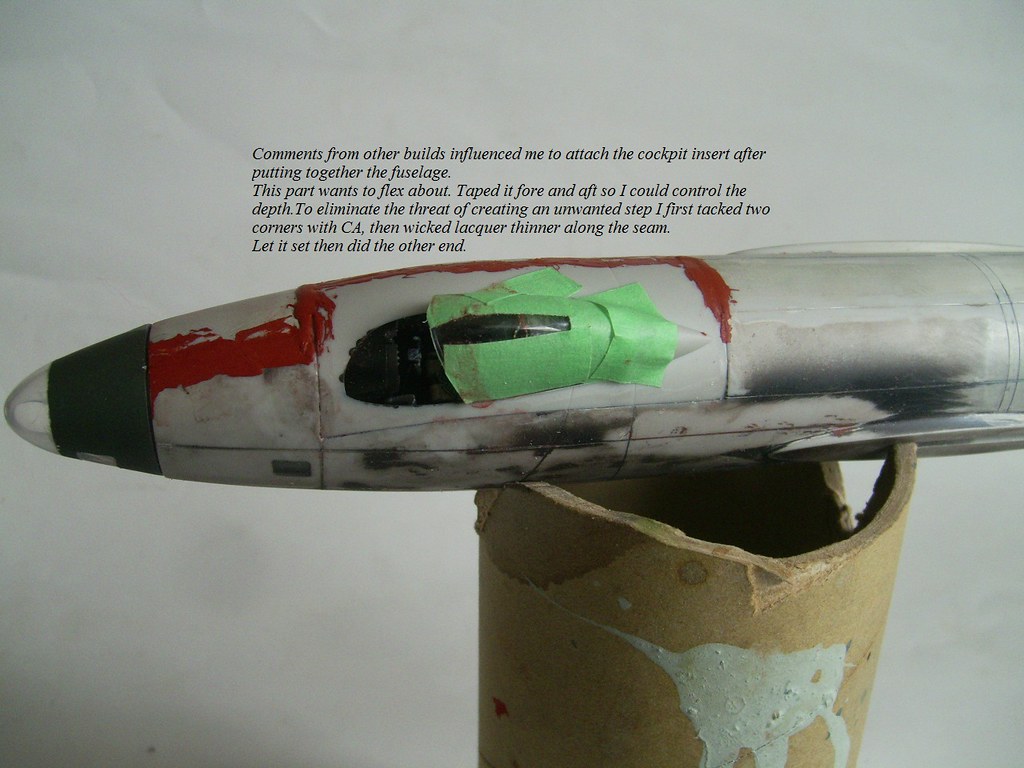 5_05 Front 5_05 Front by scap.design, on Flickr 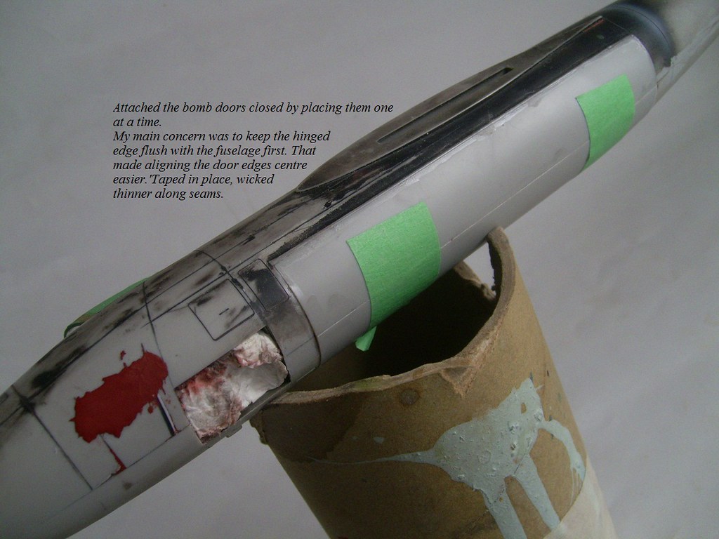 5_06 Belly 5_06 Belly by scap.design, on Flickr 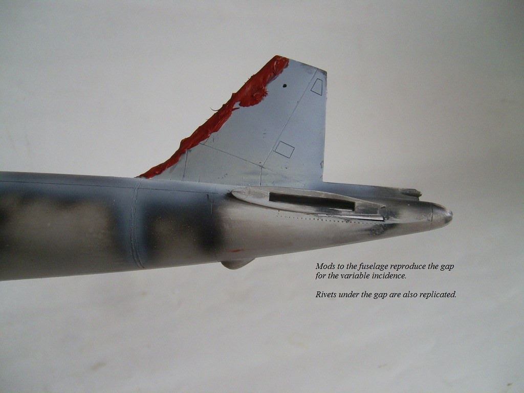 5_04 Tail 5_04 Tail by scap.design, on Flickr  6_04 Fill_Sand 2 6_04 Fill_Sand 2 by scap.design, on Flickr 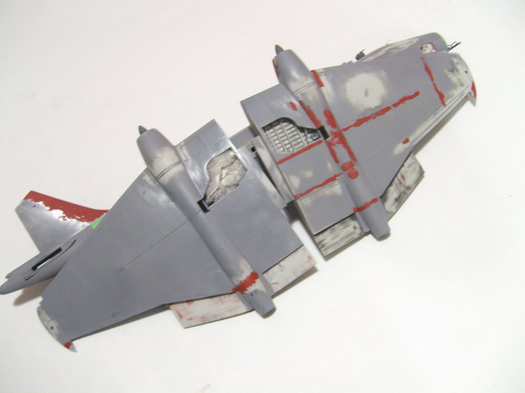 6_05 Fill_Sand 3 6_05 Fill_Sand 3 by scap.design, on Flickr All that filler around the cockpit looked rather messy. But the final seams were quite snug and left minimal gap. It still takes care to mount it flush with the fuselage, and avoid the hazard of pushing it in to far. I did, unfortunately, on the left/rear corner. Next time I'll eliminate the step with styrene.  6_03 Fill_Sand 6_03 Fill_Sand by scap.design, on Flickr But I did manage some scratch-built bits for the flap hole in the wing. Also put some brackets on the flaps. Needs only some plumbing and spar points. 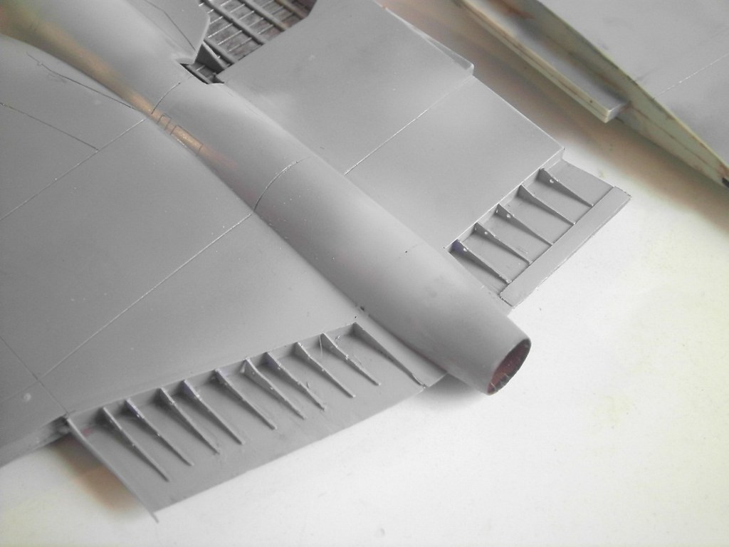 6_08 Flap 6_08 Flap by scap.design, on Flickr  6_06 Flap Structure 6_06 Flap Structure by scap.design, on Flickr 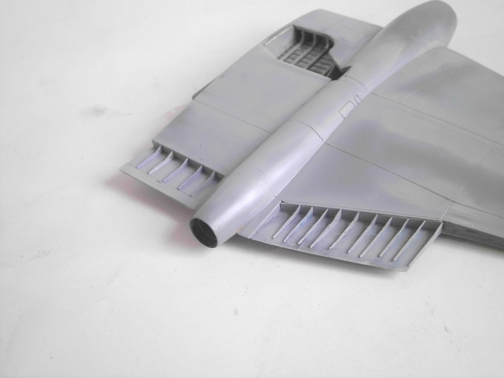 6_09 Flap 6_09 Flap by scap.design, on Flickr Canopy's now Futured and ready to attach. Nose is on and I'm beating the seam into submission. I'm dealing to the fuz and wings as separate components, for convenience's sake. When I'm happy the acreage of surface passes muster I'll put wings on. A little Academy P-51B is tagging along, too. While I wait for stuff to dry. Regards |
|
|
|
Post by Calum on May 11, 2016 14:57:59 GMT 12
Cool build.
|
|
|
|
Post by general on May 24, 2016 3:08:08 GMT 12
Gentlemen. There’s colour in Canberra. Looking more like the real thing now. I masked and painted fuselage and wings separate. Well, most of the fuz. I’ve left the rest of the paint til I’ve done the wing root seams. Dealt to the seams on the major components while still apart. It’s far easier considering how big she is together. It’s also a lot easier masking/painting the engine nacelle demarcations off the fuselage, without manipulating all that mass. Though I’d picked up a new tin of Humbrol 116 I thought I’d try an old tin of Hu 75, mixed with Hu 226 to lighten a little. The 75 is old and I didn’t realize how much crud and dried paint ended up on the bottom. Took a bit of work to stop spattering, double-straining and futtering about with viscosity. Broke out the Hu 116 for giggles and, stone me, barely any difference to the custom. Things that make you go ‘Hmmm.’ OG is courtesy of some Revell 57 I picked up in Oz. Incidentally, Humbrol 5 Gloss grey is also suggested on colour charts as close to OG. Diluted some with white for comparison. Good idea for the next one. It’ll save a gloss coat for decalling. I like Humbrol’s Polished Aluminium for NMF. Cheap and cheerful and I dilute with white to reduce the metal flake. I shoot a coat of semi-gloss clear to knock off the sheen. Works well for a scale Hi-Speed Silver. With the wings on I plonked it on the scales for research purposes. In this config she pegs out a biscuit over 340 gm. That’s one big bird. Safe to say she’s the heaviest thing across my bench by far. Masked and painted white for the main markings. Word on the street is Airfix’ markings aren’t quite as opaque as expected. With masks off I whacked it with semi-glass clear. Once dry I cut the edges with 1200-grit. That means the gloss clear for decalling will be smooth. Gone are the Halcyon days of prime/mask/paint/clear/decals. Half the work of my painting is now fine-grit wet-sanding between coats, to maintain smoothness. I do like a seamless finish. Used to be, I watched ‘Master Classes’ on vid and thought to myself, “What a lot of work. Why bother?” Now I happily plug away, years later, doing the same thing. The irony. 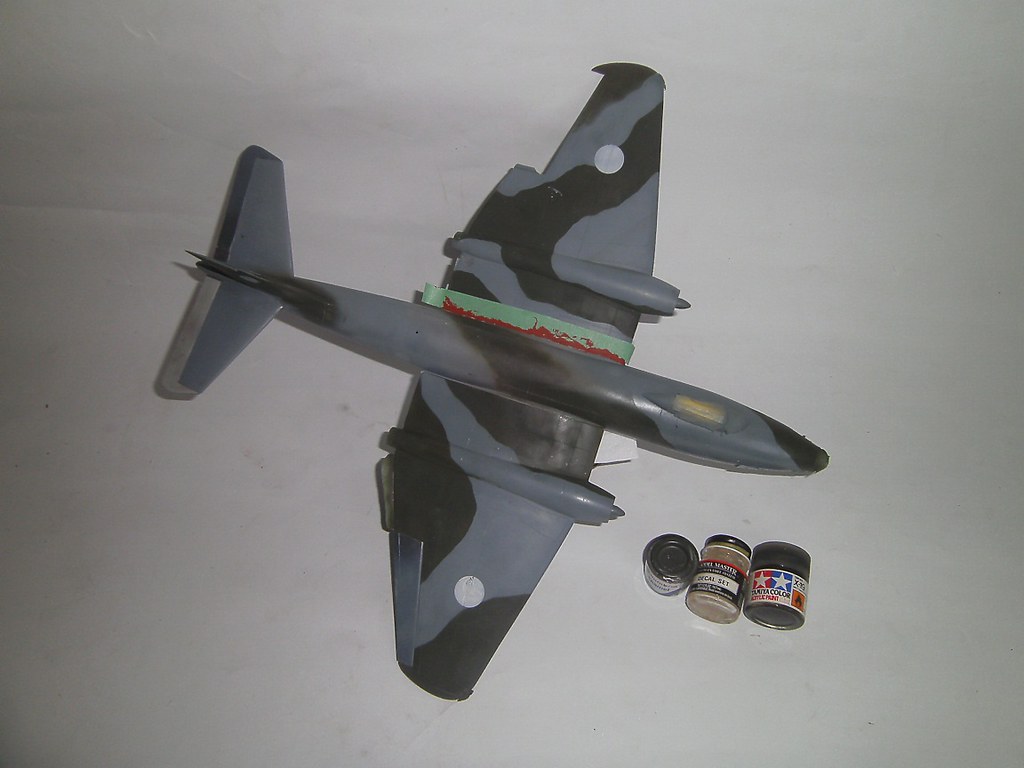 6 TopCoat 4 6 TopCoat 4 by scap.design, on Flickr 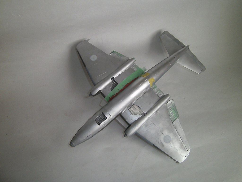 6 TopCoat 2 6 TopCoat 2 by scap.design, on Flickr Regards |
|
|
|
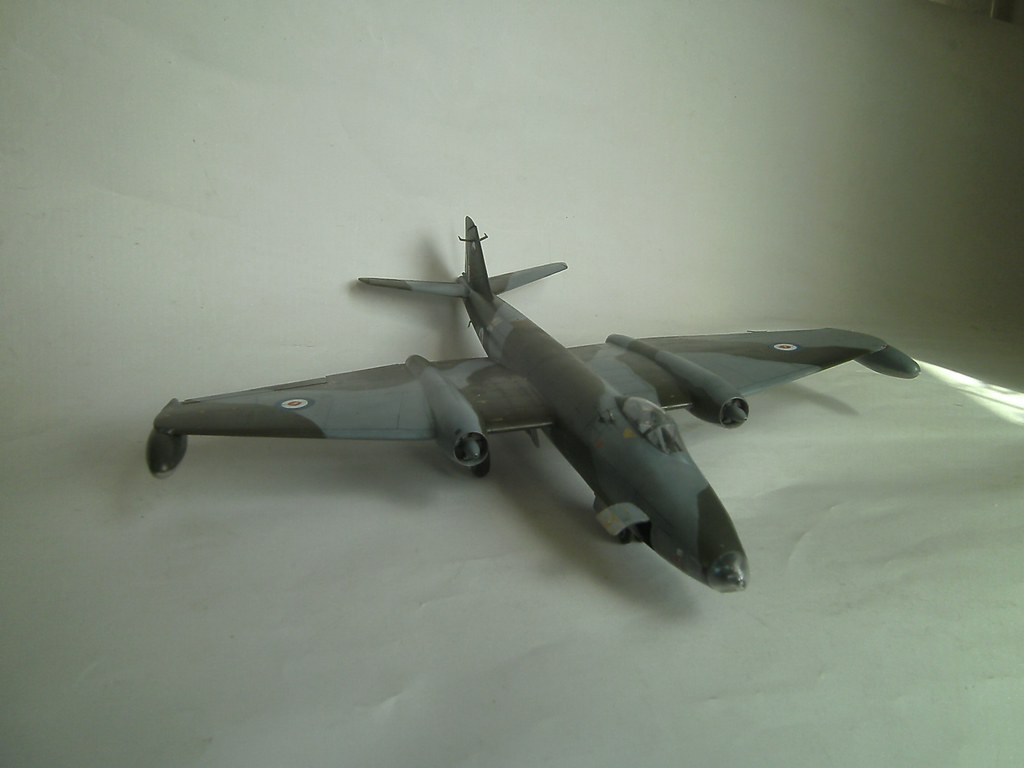
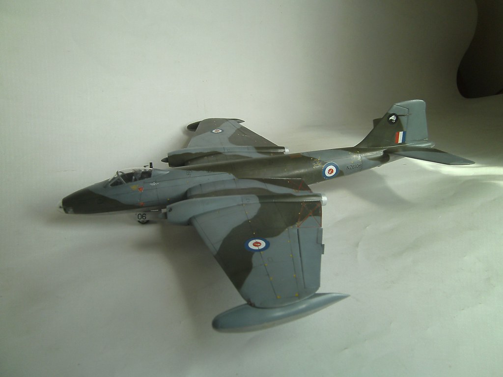
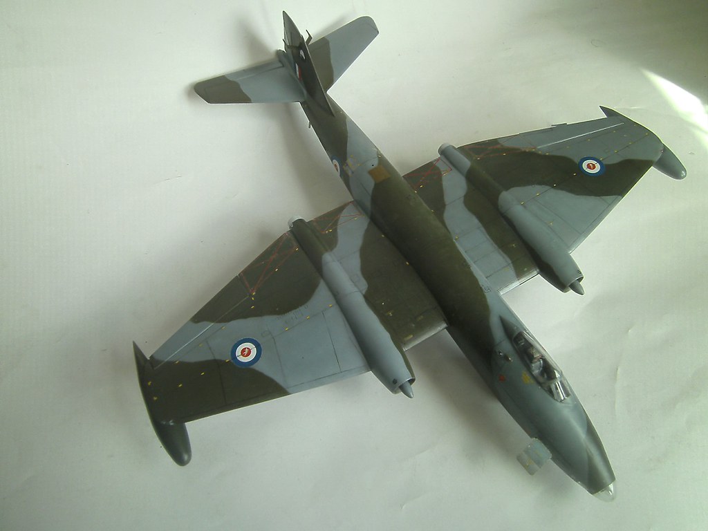
Post by general on Sept 23, 2016 19:35:32 GMT 12
|
|
|
|
Post by shorty on Sept 23, 2016 20:55:58 GMT 12
Nice model but juat a couple of points, our B(I)12s never had the aerials on the fin so those need to go and it's missing the "towel rail" aerial on the Starboard wing and during the time I was on the Squadron the rocket pod pylons were never removed. They were removed during the all silver days but not in the camouflage days
|
|
|
|
Post by general on Sept 24, 2016 3:58:21 GMT 12
Roger that, Shorty.
I had tunnel vision with the tail antennae. Winding it up with the clear coat I only then noticed some pics that showed a patent lack of them on NZ a/c. Nertz.
Doesn't worry Kevin.
Some pics did show the towel rail, some didn't. So Ieft it out.
Next time I'll add it. And the pylons.
Such is life.
Regards
|
|
|
|
Post by Ian Warren on Sept 24, 2016 9:05:54 GMT 12
That was one hell off an effort with impressive results !  |
|
itisi
Leading Aircraftman

Posts: 2 
|
Post by itisi on Apr 5, 2017 10:48:28 GMT 12
I've seen four or five online builds, even the UK IPMS Sig (a must-see before starting the Airfix). One of the first items of surgery across the board is the fin fillet. However, not one peep about a possibly narrow fin profile. In the course of research I measured up the fuselage against a couple side views, scaled to 1/48th, and the fin showed up short along the L/E about 2-2 1/2 mm. Hmmm . . . this wasn't in the movie . . . Filed a flat edge along the L/E and added scrap styrene, faired in with putty and re-shaped the contour. That put the rudder about 1mm short, but I re-profiled that according to build notes anyway. Simple fix to add a stick of sprue, filed flat on one side for a datum surface. Then shaped and gaps filled accordingly. Now I could re-shape the fillet radius. Meanwhile, what I did for the nose weight: Found some old crayons in a drawer, long time back. Lightbulb moment was, "I could melt these for cavities, make excellent mold masters". 2_01 Wax Mould by scap.design, on Flickr The bugbear of this kit is the large moment arm aft, instructions ask for 100gm over the NLG bay. Builders had dramas stuffing lead or bolts inconspicuously. I believe in 'economic use of time and resources'. Figured out where the hidden spaces were and set to casting. Overdid it a little, aft of cockpit. Figured that would be the most effective space with the bomb-bay shut. Once cast, that hunk of lead must have been closer to 300-350gm. I've since sawed off the lower 'arms' to use either side of the NLG bay. Added to the remainder of the contour weights it pegs out a smidge over 100gm. 2_02 Wax Mould by scap.design, on Flickr This is the plaster mold for the big chunk aft of cockpit. You can see the fracture line. Thought I'd cast it one solid block, then remove sprues for the pour holes and heat it in the oven to melt the wax. Stubborn cuss merely expanded rather than flowed, and split the plaster. 2_03 Plaster Casting by scap.design, on Flickr Little PITA wasn't going to defeat me. At least I could now remove most of the wax (heating with a flame to move it). White-glued it together, clamped and poured lead. I scrounge old wheel balance and fishing weights. My 'crucible' is a stainless steel cap from something, heated on the stove-top and holds about 600-700gm of lead. It's the coolest thing pouring hot lead. Turned out an ugly sucker, with all that residual wax clinging, but we only need weight, not aesthetics. 2_05 Casting Weight by scap.design, on Flickr Experience builds confidence. Onto the cockpit side cavity. I built a collapsible casting box out of CD cases a ways back. Designed to do 1/32nd SBD and 1/24th P-51D canopy masters. Simple task to blank off a suitable volume. Different strategy here. Mounted the wax master with pour stubs horizontal, and Blu-tac'd to the box wall. Plaster up to the mid-point of the stubs and set. Removed this half-casting, trimmed the surface flat and tidied up around the stubs. Back into the box and poured the second plaster. This creates a distinct line between the halves. Pulled out the stubs then put a thin saw blade through this line, around the block and through the wax. 2_04 Plaster Casting by scap.design, on Flickr Heated and cleaned out the wax - far cleaner job this time - and replaced the datum posts (old Qtip shafts). But we ain't done quite yet. An uneven saw cut would pose problems with gaps. Smeared the mating face of one plaster half with epoxy, laid down a clingfilm barrier then put halves together. Once set, off with clingfilm and we have a sealed mold. 2_06 Casting Weight by scap.design, on Flickr 2_07 Cast Weight by scap.design, on Flickr Put things together for weight and balance checks. Want to see a comparison with the Skyhawk? Taped up the Esci fuz out of curiosity. 3 Balance_and_Weight Check B by scap.design, on Flickr That'll do, for now. On to engines next . . . Regards ybiC Probably a bit late..Easy way to stop plaster of paris sticking to plaster of paris is to coat the dried portion of the mould with cooking oil. just paint on a thin layer. Easy peasy |
|
|
|
Post by sailorsid on Apr 5, 2017 20:38:27 GMT 12
Very good indeed. Another one about aerials, there was a long wire one from behind the cockpit to the top of the fin for the HF radio. keep up the great work.
|
|
skyman
Flight Lieutenant
Posts: 82
|
Post by skyman on Apr 6, 2017 17:58:05 GMT 12
As mentioned by sailorsid the wire HF aerial is attached to the fin tip but is attached at the forward end to a short blade-type attachment alongside the right rear of the pilot's canopy with another longer blade aerial (VHF/UHF?) to the right and slightly rear of the HF aerial attachment; the longer blade aerial is directly above the equipment hatch. When no step ladders were available, such as during stop-overs on a deployment and/or when there was no-one to give you a leg-up on to the wing for access to the top of the fuselage, the blade aerial was (carefully) used as a hand-hold while climbing using the battery access hatch and the equipment hatch above it as foot-holds, but this method of access was, of course, frowned on by our supervisors.
Al
|
|