|
|
Post by johnnyfalcon on Feb 15, 2021 15:57:31 GMT 12
Yeah, always love the comprehensive updates!
|
|
|
|
Post by denysjones on Feb 16, 2021 8:43:49 GMT 12
After some delving around via Google and flicking pages of old fashioned paper details of the two types of doors have come to hand. Strange as it may seem the details don't figure in the parts catalogue nor the erection and maintenance manuals but do appear in pilots notes. Firstly from the RAF AP1690 series is the door as per 2035  and secondly from the US T.O. 01-75AB that as per 2049  Interesting is that it appears that the CO2 bottle remains in the enclosure of the second type whilst in the first it appears to exit in company with the dinghy. The latter sort of makes sense to me as the dinghy can't inflate in the door cavity but why not just supply longer inflation tubing which must be what the later type does? So now I better understand where things go but sadly more importantly what's missing. cheers |
|
|
|
Post by davidd on Feb 16, 2021 9:17:48 GMT 12
As with RNZAF Hudsons, all those shipped (or ferried) to the UK had no operational equipment fitted at factory, as this was to be supplied (by RAF) and installed by the designated civil contractor after arrival (was this at Prestwick?) From RNZAF records it is apparent that no American radio gear, safety equipment, armament equipment or radio gear was shipped with our aircraft (although the later Lend-Lease ones had American Bendix radio equipment). The RAF would have had to obtain permanent or temporary radio and navigation gear to equip those aircraft being ferried across the North Atlantic. Not so difficult for those ferried to RCAF of course, although they probably were fitted with some kind of radio.
David D
|
|
|
|
Post by denysjones on Feb 20, 2021 20:59:00 GMT 12
Evening fans, A quiet day at the factory today as there was some tedious building R&M works to be going on with...damn shame when you have to build and maintain the premises where you get to do all this stuff but better we did that job today rather than have a water feed fracture and flood the workshop! Anyway later in the day attention turned to the other side of the door on 2035 and the matter of the stay that holds the door open. Somewhere back in time (amazing how so much is "back in time") said stay got broken leaving the mounting end in the door structure and part of said structure and the stay out in the wild. So in lieu of massive disassembly of the door I took to cutting a sliver out of the side frame to extricated the remains trapped therein (as arrowed here)...developments will follow.  After that the balance of the day was sanding and priming the door surface. For the enthusiasts you'll note here the remains of the RNZAF interior colour showing as a distinctly blue shade over the Lockheed green and zinc chromate. ttfn |
|
|
|
Post by Dave Homewood on Feb 22, 2021 10:50:07 GMT 12
Interesting to see the different colours, for sure.
What did the wording say? Is that CHUT, as on part of PARACHTE? (And EXIT)
|
|
|
|
Post by denysjones on Feb 24, 2021 9:18:35 GMT 12
You're quite right with your guess of the wording Dave. It was red on a white panel and Owen our friendly computer graphics man is on the case with the replacement. (Owen visited us one day with his family and came forward with the offer that anything in that vein we wanted he would do for us on a materials only basis ...real great when people make offers like that!). He's the one who made the "turn & lift" placards for the floor hatches recently, all 16 of which are now done. Another decal was so faint it didn't show up but it was a thin red bordered box with the words DINGHY RELEASE in it. Owen's across that as well and it will go to the left of the tubular fitting just a bit lower down on the door. That's where the pull wire from the cabin enters the dinghy stowage to activate the inflation. The opening below that is where the electrical connection for the immersion circuit fits. Here's how operation door stay is progressing..namely kitset on the bench.  You see that Lockheed folded up an open top box and riveted it on top of a flat metal plate with a tongue on it. This assembly was fed into the door structure from what is the outside face, tongue out through the slot I enlargened to remove the assembly out the back so to speak, and riveted around three sides. Then when the door's outer skin went on two screws through it picked up the two captive nuts. Obviously they never thought you'd need to get the unit out, well not easily! The stay's slit then slid onto the tongue and was held by a pin. The fracture of our tongue occurred right on the point where it exited the skin and I can't figure out what event would have done it as I recall the stay being functional when we first got 2035. Never mind I've made the replacement piece and reassembly will commence! I've just two probs at the mo with the stay. The engagement lug at the left is well rusted and so is the screw holding it in (recessed from the top). The other is at the left end of the slit there is a sprung loaded ball bearing housed back in the body which provides a lock effect with the concave in the end of the tongue. I've got the ball bearing out but the spring is resisting my efforts so far. ttfn |
|
|
|
Post by ZacYates on Feb 24, 2021 14:03:06 GMT 12
I may not comment but I always enjoy each and every update from the Ferrymead time. I just want it known my "Like"s are sincere!
|
|
|
|
Post by denysjones on Feb 27, 2021 20:29:30 GMT 12
I finally overcame the two problems with the stay after a good soak in our old friend vinegar followed by some CRC so both the spring and stay catch came to the party. So today things went back into the repainted door and Owen's graphics dressed it off nicely, or to quote one of our beloved helicopter team "as flash as a rat with a gold tooth". However a wee bit of an oops acme to attention During the week I masked off the white backdrop to the main wording, sprayed it, then reverse masked it, if you get my drift, and then painted the door. Today I applied the graphics and stood back to admire my product and it turned out that the original white band as I followed it was not entirely true but was just under 1/8" of an inch deeper at the right end than the left and so when I aligned the letters relative to the top line we end up with a distorted effect.  However as we've followed the original bounds we'll run with it as who can disprove that it was/wasn't an original error! The next puzzle if how the dinghy release cable was shrouded. You can see I've run it out to the dor but I'm sure it must have been in some casing to protect it and as the end of the fitting on the door is stepped which suggests something was secured to it by way of a strapping. Other good news today is that we are close to securing a swap deal which involves an Aussie buying some ultra hard to find Pesco hydraulic relief valves to swap for a surplus radio set we have, total value around the $NZ450 mark, and bringing the items left to finish the hydraulic/fuel control bay down to a mere handful now..  |
|
|
|
Post by Dave Homewood on Mar 4, 2021 15:40:43 GMT 12
That door has come up looking fantastic!
|
|
|
|
Post by agile on Mar 7, 2021 16:41:32 GMT 12
Thanks for all the kind words above. Also HUGE thanks to Dylan Stace, who acquired and donated a mint condition British drift recorder to the Mosquito project in response to my previous post. The Big Repair continues to move forwards along the starboard side of the fuselage towards the cockpit door: 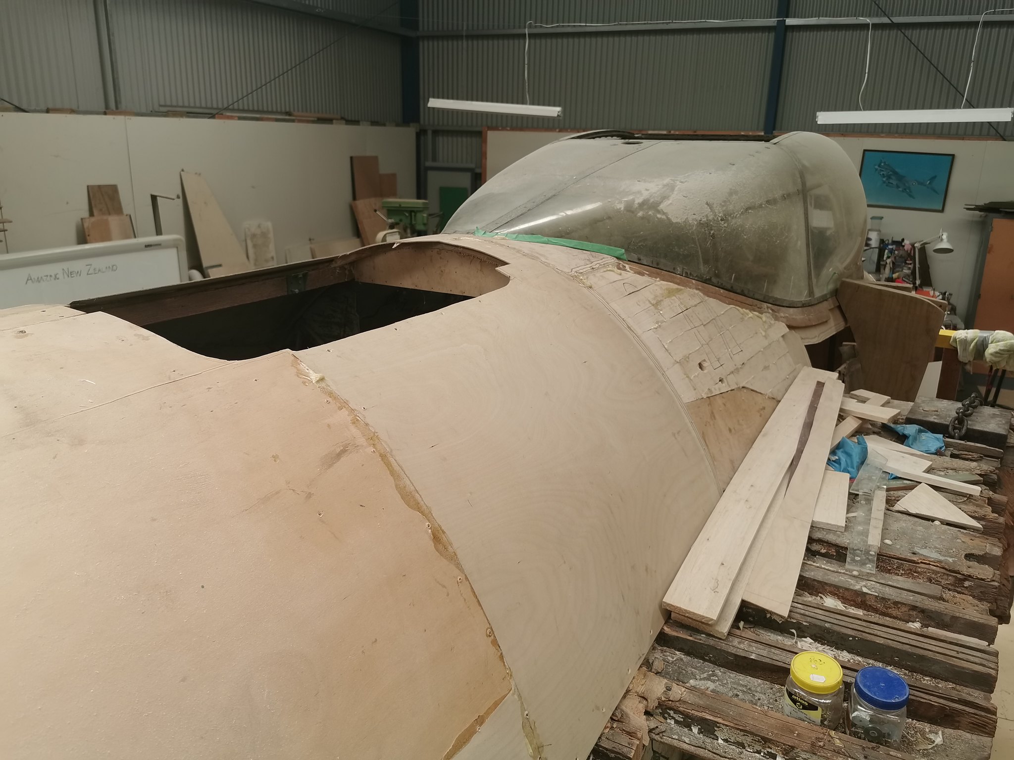  Where the structure curves around the opening ahead of the mainspar, the spruce former is completely rotted away, and has been replaced based upon the original drawings. The large hole under the main spar is in the removeable panel under the wing, which we'll repair on the bench when we have removed the centre section. Note also the large plywood profiles bolted to the outside of the fuselage - these are based on the opposite side of the fuselage and will ensure that the new structure matches the curve of the original:  We have rather a lot of paxoline/tuffnol spare bits accumulated from various sources, including those pictured below. Distinctive amongst these are the triangular VHF aerial insulators, the parts with the aerofoil shaped cutouts which are associated with the trailing aerial, and the L-shaped bits at the bottom of the pic, which are Gee aerial insulators. These last are a particularly curious thing to find in NZ:  At the bottom of all this stuff was one single NOS example of the VHF earth bar insulator - phew!: 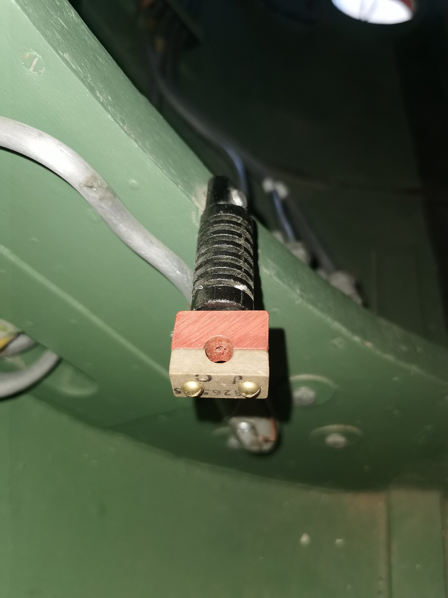 Dagy has assembled a set of 3 VHF aerial elements from the original drawings (these are brass tubes with a brass plug sweated into one end and a threaded brass road sweated into the other) and these have now been installed in the rear fuselage:  Last but by no means least, new recruit Tyrone has very neatly manufactured the bracket which holds the lamp fairing onto the tailcone, using a pair of rare floating 4BA anchor nuts filched from the fuselage remains of HR339. We had the lamp but not the base. A quick SOS to Austers-R-Us and a fast motorcycle ride out to casa Galbraith yielded the missing lamp base and a bulb - thanks mate!!: 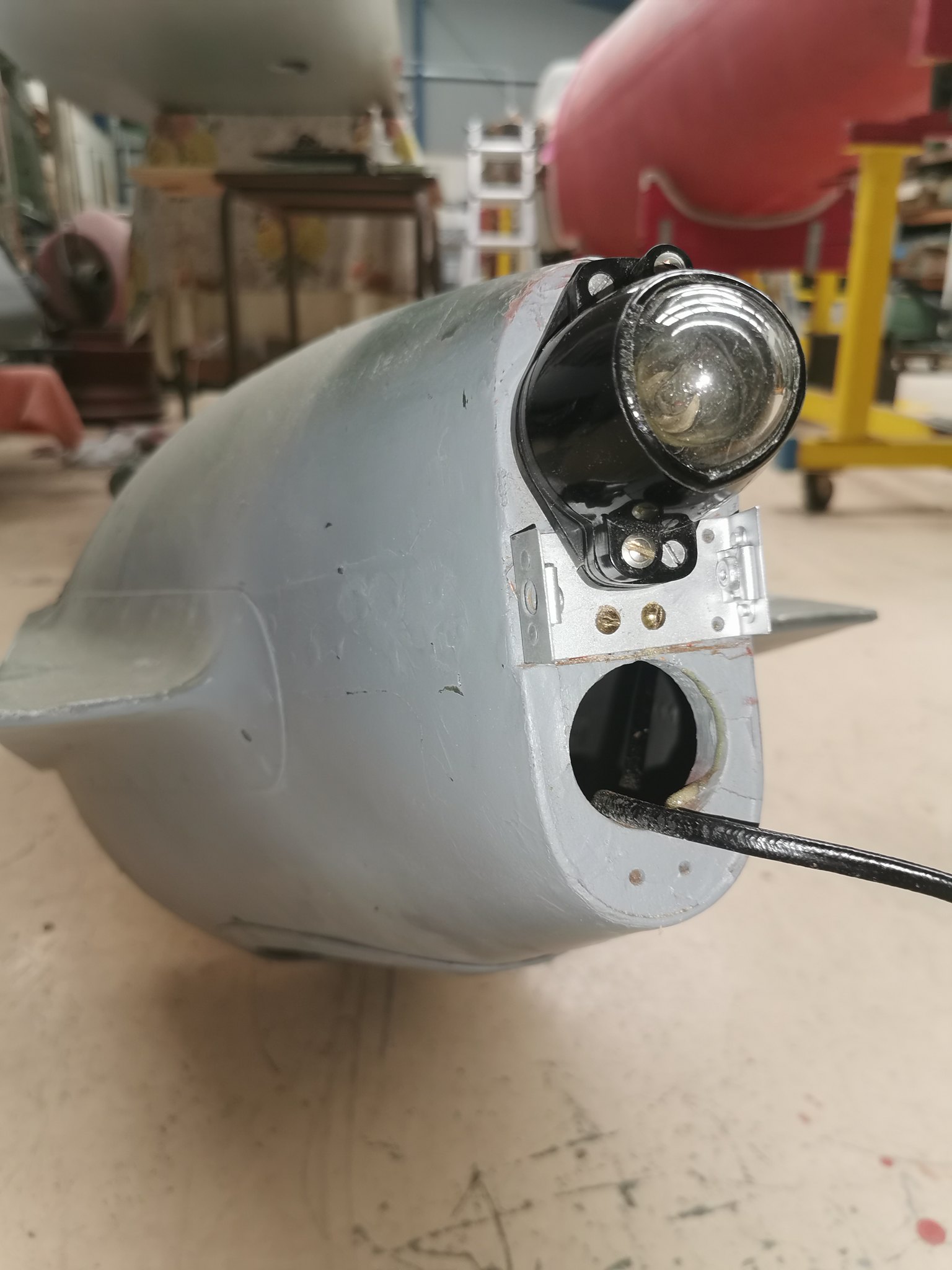 The lamp fairing, which came from Tony Agar is now installed temporarily. The lower aperture should house a 'resin' lamp, but we are unsure as yet how this is fitted:  Thanks again to all those following along with our various projects. Cheers A |
|
|
|
Post by aircraftclocks on Mar 7, 2021 19:13:15 GMT 12
The following may assist with the resin lamp fitment.
A.P.1095A. Vol. I, Sect. 8
CHAPTER 11
COLOURED RESIN RECOGNITION LAMPS, Types A and B
Introduction
1. When flying at night, aircraft must be equipped with some means of formation-keeping and identification that is visible to other aircraft at approximately the same level, but invisible from the ground. Coloured recognition lamps, types A and B, sometimes known as "Resin" lamps are designed for this purpose.
2. The following table gives a list of the accessories and spare parts available.
Recognition lamp, type A Less filter screen Stores Ref. 5C/1914
Recognition lamp, type A With clear screen Stores Ref. 5C/918
Recognition lamp, type B With blue screen Stores Ref. 5C/803
Filter screens Red Stores Ref. 5C/1917
Green Stores Ref. 5C/1916
White Stores Ref. 5C/1918
Adapter For type B lamp Stores Ref. 5C/1919
Lamp socket Bakelite Stores Ref. 5C/793
Filament lamp 4 watt 12 volt Stores Ref. 5L/2075
4 watt 24 volt Stores Ref. 5L/2076
DESCRIPTION
Type A
3. An illustration of the type A lamp, which is 2.75 in. long, 1.18 in. in diameter, and weighs 2 oz. is given in fig. 1, and fig. 2 shows the range of visibility of the lights together with the position in which they are mounted on the aircraft. A bakelite lamp socket (2) of the standard spring loaded plunger type is employed, the skirt being drilled and tapped at diametrically opposite points to take two 6 B.A. fixing screws for securing the fitting to the airframe (4). The brass filter screen holder (5) fits over the lamp socket to which it is attached by two 6 B.A. countersunk screws (3). The filter screen (7) is a sliding fit in its holder, and has three small raised punchings which engage behind the recessed end of the holder and act as a snap fastening. A raised portion (6) fits into a slot cut in the holder, thus ensuring assembly in one position only. The glass is secured by a circular spring clip which fits into a groove in the end of the filter screen (1).
Type B
4. The coloured recognition lamp, type B, is a modification of the formation-keeping lamp, type B (Stores Ref. 5C/803), and is used on existing types of aircraft, new types being fitted with the type A lamp described in the preceding paragraph. To convert existing lamps, it is necessary to remove the blue glass dome and the screen cap by withdrawing the two 6 B.A. fixing screws and substituting a metal adaptor and a filter cap similar to that used with the type A lamp, after which the fixing screws should be replaced. The 6-watt filament lamp should also be removed and replaced with a 4-watt lamp of the correct voltage.
INSTALLATION
5. The lamps are mounted on the trailing edge of the wing tip, either externally, or behind transparent windows in the position indicated in fig. 2. The angular range of visibility may also be seen in this illustration, and the lamps are so positioned that obstruction by the air-frame is reduced to a minimum. Two holes, tapped to take 6 B.A. screws, and situated on either side of the lamp socket, are used for securing the type A lamp to the aircraft. When this method of fixing is employed, care should be taken to see that the fixing screws do not project through the skirt of the lamp socket, or difficulty will be experienced when inserting the filament lamps.
1. Screen (end view)
2. Bakelite lamp socket
3. Countersunk screws
4. Fixing holes
5. Screen holder
6. Locating key
7. Filter screen
6. With the coloured recognition lamp, type B, the bracket with which the old formation-keeping lamp, type B, is equipped is still retained, and the method of fixing will remain the same. Where this lamp is fitted externally, care should be taken to see that all sharp corners are removed on the cable entry holes. There is one lamp fitted in each wing tip on small aircraft, positioned as shown in fig. 2, and as three screens, clear, red, and green are required for each lamp, stowage will be needed for the screens that are not in use. Stowage boxes for filter screens are provided in which the spare screens can be kept and these should be mounted in a convenient position, two holes to take 4 B.A. fixing screws being provided for this purpose. Larger aircraft have three lamps mounted on each wing.
OPERATION
7. A switch box, type B, is used for controlling the lamps, and by use of the appropriate screen, a clear or coloured light may be shown or, on aircraft where three lamps are fitted on each wing, the desired colour may be selected by means of a selector switchbox, type A, the circuit being so wired that only one colour can be employed at a time.
SERVICING
8. The operation of the lamps should be checked by switching them on and ascertaining that they light, and the glasses and bulbs should be kept clean. Access to the filament lamp is obtained by removing the filter screen, and the lamp should be replaced when the glass shows signs of discolouration. The lamp socket plungers must be kept clean and should show no signs of sticking.
|
|
|
|
Post by agile on Mar 7, 2021 19:18:58 GMT 12
Thanks Aircraftclocks, that's good info. We have the lamps, and the wingtip installation is fairly straightforward. We also have the box and the spare filters. The crux of the biscuit though is that AP2019E shows a third resin lamp in the tailcone, and it's the mounting of this that is a mystery.
|
|
|
|
Post by aircraftclocks on Mar 7, 2021 19:45:06 GMT 12
I have an illustration of how the 3 are fitted to the wing tip of a Lancaster, if that would help?
|
|
|
|
Post by ZacYates on Mar 7, 2021 22:26:26 GMT 12
Fascinating stuff, it's amazing to see how good she looks inside. Some great finds/acquisitions in there too!
|
|
|
|
Post by denysjones on Mar 13, 2021 19:49:51 GMT 12
Hello, Saturday night and here's the report from today's coal face! This week the two Pesco 224-C relief valves for the Hudson hydraulics arrived from the USA so this took me back to the familiar hell hole under the pilot's floor. In this shot you can see three rectangular units mounted in the upper left foreground, two together forward, and one further to the rear. 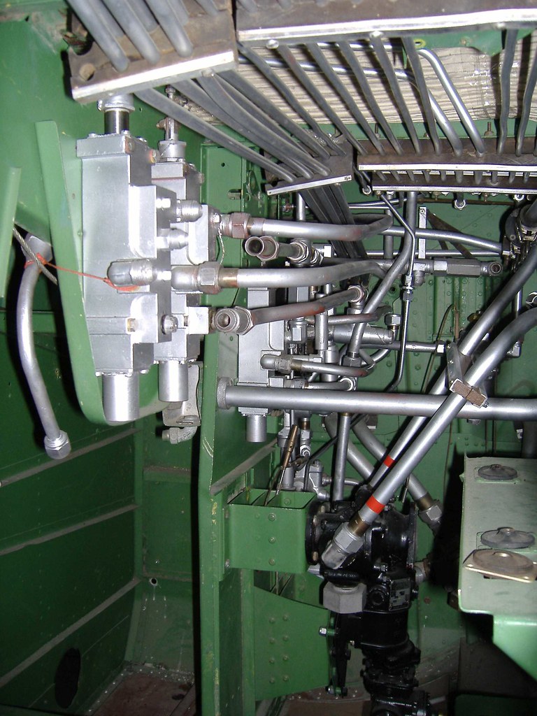 These are the 4-way valves that control the three major hydraulic systems in the a/c being (from front to rear) wing flaps, landing gear, and bombdoors. Each valve has four ports on it which logically group into pairs with each pair controlling a function of the circuit. For example "gear up" and "gear down" for the landing gear. The relief valves sit across the circuit as a whole but physically are at the front of this area. Well they are now after removing the 4-way valve from the a/c to attach them and a couple of pieces of other plumbing to work around getting it back. All the illustrations in the various manuals portray the relief valves as sitting vertically whereas the IPC shows them inclined. I'd always thought that was just for the purposes of illustration but now I know better, hopefully the inclination will be visible in the piccie.  I can't imagine what it would have been like working on this area in an a/c baking in the pacific sun. There's a bit more plumbing to complete things but the issue is a few elusive items, as always, and we welcome any number of donations especially if you have AC811 fittings you don't need we'll give them a good home.! (one day I'll either get it all together or cease to be a pedant!) cheers |
|
|
|
Post by denysjones on Mar 20, 2021 20:20:39 GMT 12
Sorry folks no pretty picies this week, the works not being super photo-genic.
The first task was the follow-on from last week's valve installation in the fabrication of the lines from the two valves rearwards to the bulkhead unions (back of last week's photo) thence to the flap ram in the main cabin. You can see the two rearwards facing elbows on the bottom of the new valves, especially the one foremost in the photo.
Lucky I'm a skinny dude but was still a struggle to measure up and make and install those lines! Hopefully my back and neck will get over it.
This even involved a grinding modification to a spanner to fit the closed space to tighten up the nuts on the lines at the bulkhead.
Planning to move onto the next project was interrupted by a drop of parts from Laurie Gudsell who is a supporter of 633 Sqn (aka mossie project team) but which turned out to also figure numerous non mosquito items.
So these things came my way and so time was spent in delving into them.
Then we got back on agenda which was sorting out more Hudson plumbing items.
I'm having to do this by measuring said items (length and diameter) and then trawling the tables for piping in the erection and repair manual to (hopefully) id them and thence to trace their role in the aircraft.
A lot came with 2035 but others came from the purchases from the infamous scrapyard post NZ2031 incident hence there being the need to pursue this path of evaluation! However we'll get there.
ttfn
|
|
|
|
Post by davidd on Mar 21, 2021 9:24:01 GMT 12
Great stuff Denys, always closely following progress on all your "patients", but especially Hudson and Mossie.
David D
|
|
|
|
Post by baz62 on Mar 21, 2021 10:16:28 GMT 12
You are doing a fantastic job putting all the hydraulics back in as it used to be. Are there any plans to get any of it operational? Funnily enough I work for a company who (among other things) make hydraulic manifolds and some ancillary parts for various hydraulic companies. As part of the Group of companies we recently bought is a Seal company (no not the aquatic kind....). Anyway if you were looking to make something live and needed something in the oil seal line that you were having trouble locating drop me a message.
|
|
|
|
Post by ozfuryfan on Mar 21, 2021 13:36:55 GMT 12
Interesting Baz, can they mfg seals fur use in mil h 5606 hyd fluid, can they make per sample or do they need a dwg, might have a few that need doing, Pete
|
|
|
|
Post by baz62 on Mar 21, 2021 16:15:49 GMT 12
Interesting Baz, can they mfg seals fur use in mil h 5606 hyd fluid, can they make per sample or do they need a dwg, might have a few that need doing, Pete I'll ask the seal man tomorrow.  |
|