|
|
Post by denysjones on Feb 5, 2022 20:40:14 GMT 12
Another quiet day at the coal face. Dreary weather meant a very low visitor count and various absentees from the work force due the long weekend. During the week the de-icer tank got finished when our graphics guru Owen's graphics got applied to the filler cap, followed by tidy up of the Lockheed plate on the face, which finished off the physical tank refurb. Next the mounting straps etc have to get sorted and then installation will follow. 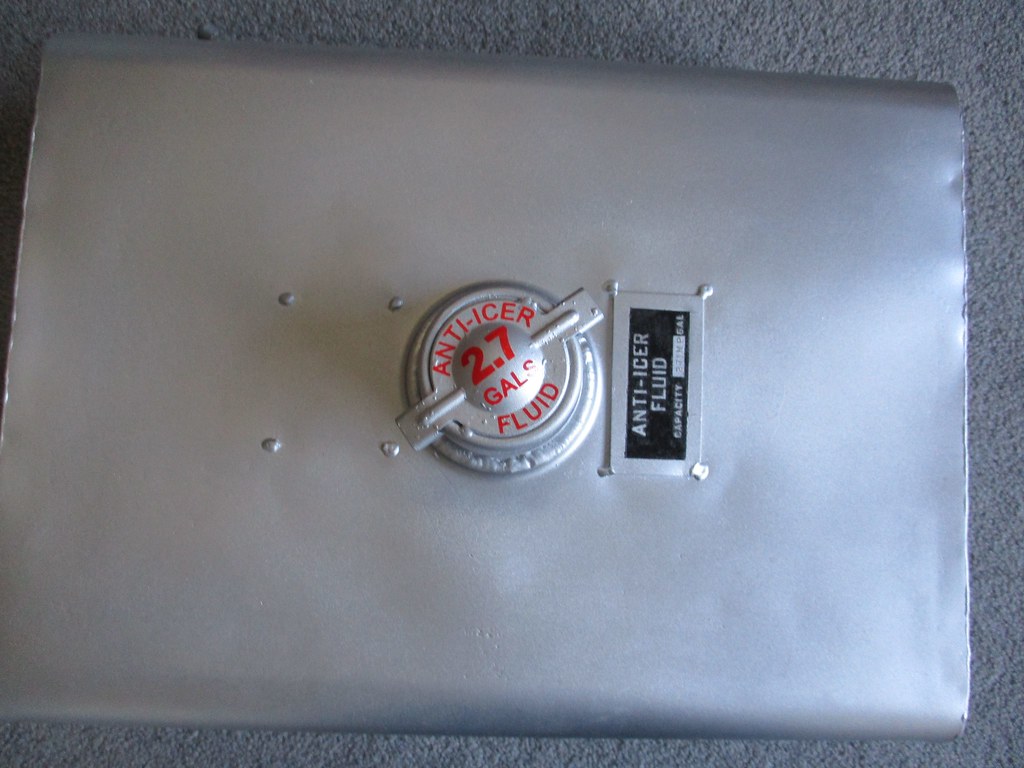 First up today I got the holes in the connections manifold through the firewall drilled out and then the appropriate fitting installed for said, now painted, plumbing fabricated as described last week. P clamps as appropriate were then cleaned for attachment to engine frame members, which themselves have had mid-week titivation. Cleaning of genuine Lockheed turnbuckle style clamps and rubber joiners then followed next. Thus finally in we go with the input feed to the first vacuum pump. 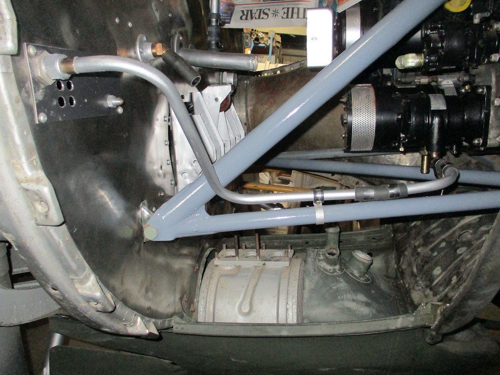 Later we moved on to the makeup of the corresponding tubes from the manifold but this time the to and from the hydraulic pump...buts that's for times to come. ttfn |
|
|
|
Post by denysjones on Feb 9, 2022 10:14:26 GMT 12
A mid week post in relief of quietness on the forum page today, to show an example of the sorts of inventiveness that sometimes has to come into play seeing we don't have all the tooling they had at Lockheed Burbank! The other week while I was busily sorting out plumbing projects I commented to Dean, who had dropped by, that I was needing to make some larger diameter pipes that required beaded ends to be formed on them for rubber clamped joins. My problem was that at 1 1/2inches diameter (approx 38mm for you metrics) they were far larger than any Crox tool that I have in my arsenal of such weapons, and have used on smaller sizes. Dean surveyed the material, muttered a few choice epithets, and departed with a sample of tube in hand. On Saturday he returned with the product of some time in the workshop at home and presented me with the Heath-Boston Mk 1 .... 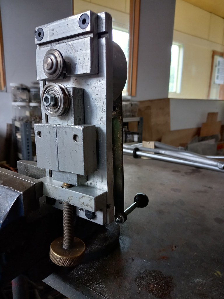 The creation is widely adjustable over a generous range and so allows us to form a bead on all the sizes we foresee we'll need. The material is placed over the upper roller and the bottom fitting screwed up against the exterior and then pipe and rear handle turned and Bob's your Uncle the bead forms in stages as you do repeated revolutions progressively continuing to screw the bottom unit up until you're happy with the amount raised above the tube surface.  Well done that man. |
|
|
|
Post by davidd on Feb 15, 2022 11:48:24 GMT 12
Wonderful stuff Denys (pass on congratulations to Dean!)
|
|
|
|
Post by ZacYates on Feb 17, 2022 17:22:50 GMT 12
Hear hear!
|
|
|
|
Post by denysjones on Feb 19, 2022 20:23:20 GMT 12
Another week of small KaiZan steps for 2035 ... The home workshop bits from last week saw a refurbished fuel pump today restored onto the port engine on the right of shot here, along with the first half of the feed back plumbing to the firewall from it. 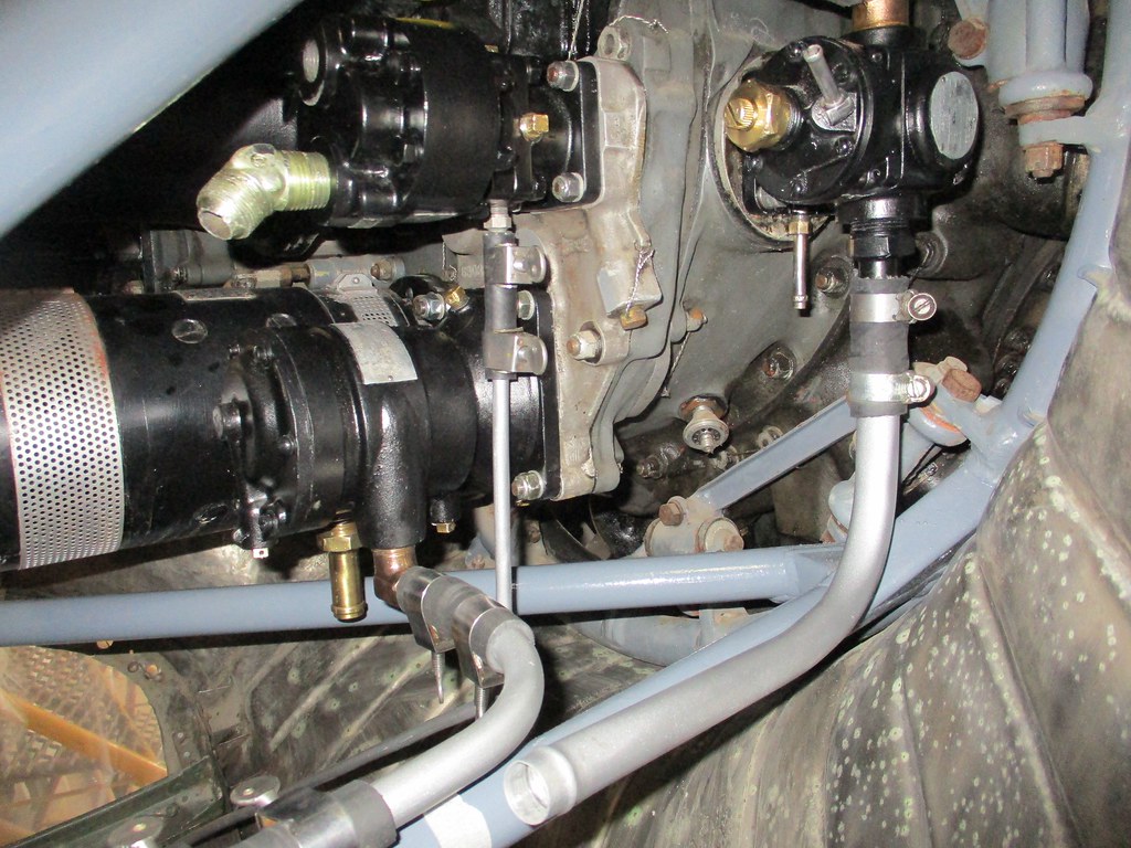 At the same level but to the left is the hydraulic pump and off it now is the slender drain down to atmosphere out the left side of the cowl scoop. Most if not all of these plumbing bits can then be duplicated for the starboard but of course almost 50-50 can not! On the starboard side in the aft of firewall zone the oil tank Y-valve got mated up with the first half of it's feed through to the firewall. 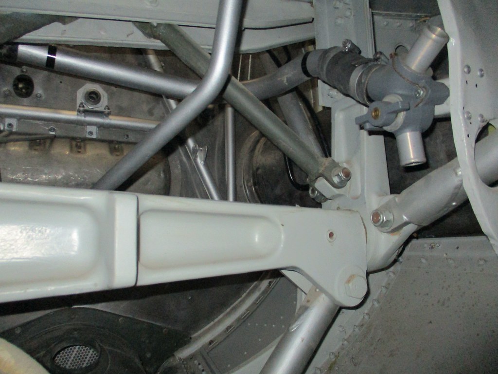 Thereafter more bits and pieces of prep work for this week's home stuff...see ya  |
|
|
|
Post by baz62 on Feb 20, 2022 10:31:32 GMT 12
Looking great Denys. I presume although everything is hooked up this will be static only? Although I suppose you could get the hyradulic system working.........then you'd have a reason to put drip trays underneath!  |
|
catcrew
Flight Lieutenant

Posts: 72
|
Post by catcrew on Feb 20, 2022 21:14:37 GMT 12
If it has radials, and every good aircraft has, it needs drip trays. I've seen radials that haven't run for decades that still need drip trays.
It must be said that restorers that make such an effort to make a static as authentic as possible, including these areas that would not normally be looked at by most visitors, are very special folk. It is easy to get enthusiastic about a restoration the will fly, but to those at Ferrymead that take as much pains in their restoration as shown by the notes here, you have to take your hat off to them. Ferrymead is a must visit museum and I look forward to my next visit when I cross the ditch.
|
|
|
|
Post by denysjones on Feb 26, 2022 20:45:00 GMT 12
A very quiet day work numberswise today...not sure where 633 Sqn were (name a bit of in-house humour) but on other fronts others soldiered on.
Hudson front was a mirror image of last week's report in that now the stbd engine has it's fuel pump and hydraulic drain pipe installed. So the rest of the day was cross-relating IPC drawings and E&M manual pages and trying to arrive at the correct lines and makeup of other plumbing. Off to this week's home work with four more items to finish and ready for installation next week.
On the installation front Paul was busy down in the C47 hangar on the backdrop work for a new installation that will take place in a couple of weeks. Installation in the sort of art type sense and subject related to two threads running elsewhere here on as in penguins and Operation Deep Freeze...wait for it!
|
|
|
|
Post by ZacYates on Mar 4, 2022 7:22:35 GMT 12
On the installation front Paul was busy down in the C47 hangar on the backdrop work for a new installation that will take place in a couple of weeks. Installation in the sort of art type sense and subject related to two threads running elsewhere here on as in penguins and Operation Deep Freeze...wait for it! That sounds excellent! |
|
|
|
Post by denysjones on Mar 5, 2022 19:33:58 GMT 12
Still more small steps this week with again a small team on site due to Covid stuff. The results of the week's home workshop stuff continue the progress on the engine plumbing of 2035, times two but just one side's photo, here port. 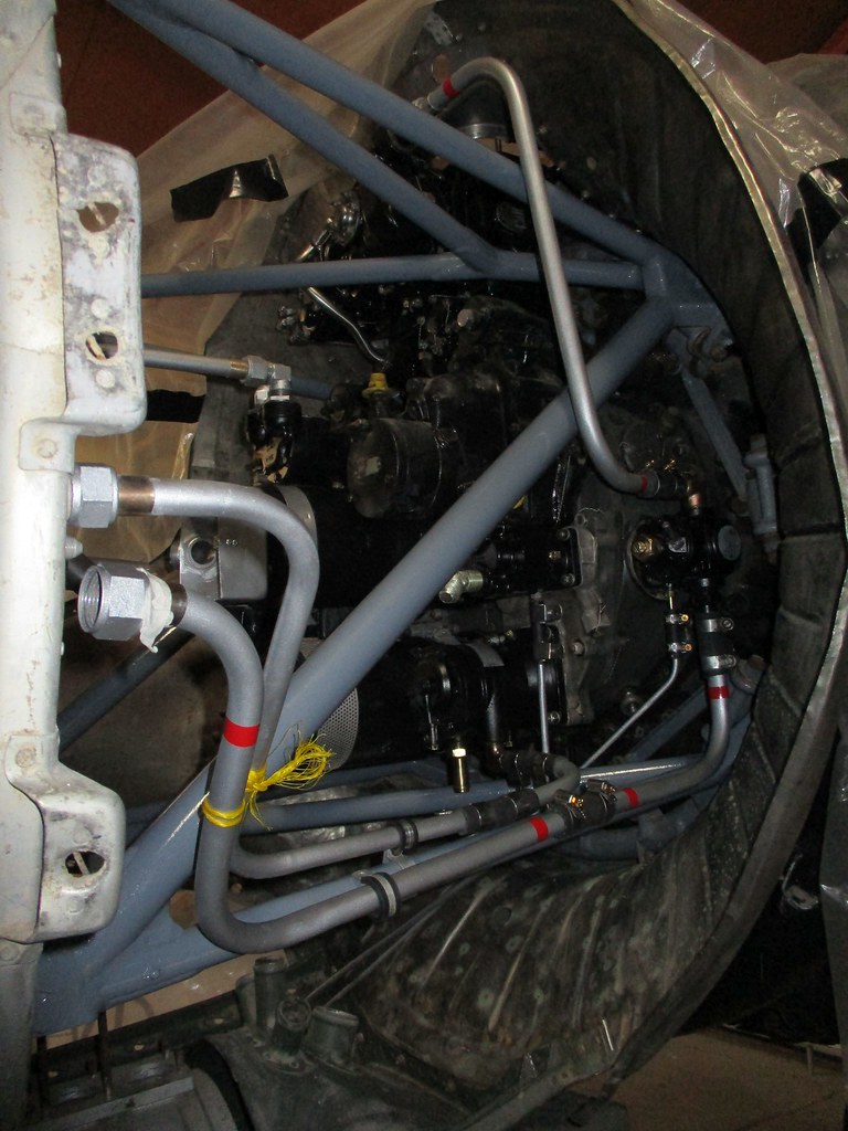 Thus we've now got the line from the fuel pump up to the carburettor, and from the fuel pump the drain goes out and left (as in photo) to atmosphere in company with the one from the hydraulic pump, as seen below the engine frame members. The second leg of the feed to the fuel pump is now hanging in there across the bottom of the shot, currently tied up with the yellow line pending this week's prep of the union through the firewall for it to join to. One of the conundrums of the week concerns the suction gauge feed to the instrument panel. This is, path of which aside, why is there only a feed from the starboard engine? Any one out there able to explain this it doesn't seem to make much sense to only monitor just one engine ? cheers |
|
|
|
Post by oj on Mar 5, 2022 19:59:24 GMT 12
Can you please tell me the brand, model no. and electrical rating of the generator?
|
|
|
|
Post by denysjones on Mar 12, 2022 20:08:04 GMT 12
Work on the home front this week centred around matters of the connections through the firewall manifold. There are some twelve connections passing through there (twelve on the starboard and eleven on the port due to the suction matter mentioned last week) catering for five different sizes of tubes. By far the most numerous size on each firewall are for 1/4" tubes for such as oil and fuel pressure and carburetor deicing. There are eight on the starboard and seven on the port of these. Dealing to the 1/4" ones first I found we had seven suitable unions in stock, being AC811 series items, so needed eight more. Searching extensively internally and externally for more drew no solution. I contemplated resorting to AN series units but there is considerable visual difference even after a Dulux overhaul to change their colour and the pedant in me resisted that path. So this week I tried some suitable aluminium rod with the appropriate thread cut onto it and some likewise right sized nuts, which got drilled out and tapped to the right thread (7/16 NF 20) just to also be tricky but fortunately I must have met that thread on the a/c somewhere in the past and so had purchased die and tap for it which were on hand at home. The result passes my personal critique (I didn't bore them out as we're not intending their actual use) so here are two along with my pattern real McCoy (its the one in the middle). Now just six more to knock up. By way of comparison the one at the top of the photo is for a line joiner for a fuel line and so the corresponding union has to be the same size thereof ....different technique required to solve this one! 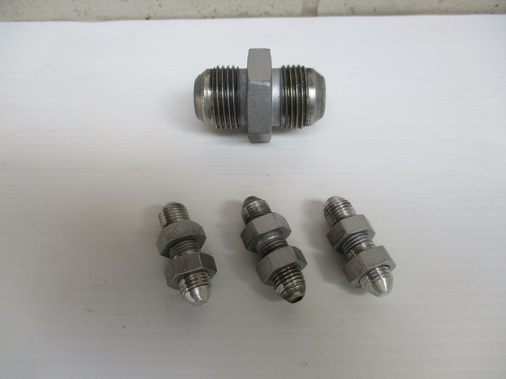 So today was moving onto the task of interpretation of the tubing tables to fabricate lines from these unions off to the engines for their various functions..something hopefully for next week |
|
|
|
Post by denysjones on Mar 19, 2022 18:51:38 GMT 12
Another day of slow tedious plumbing stuff on the Hudson front. First up was the oil tank vent connections from the engines to the firewalls whereafter it goes back to the tank. One went ok ... just remove a reducing step from the engine and install the appropriate (correct) size unit to make said connection and there's the pipe in place, just the pipe clamps on the firewall end to fit. 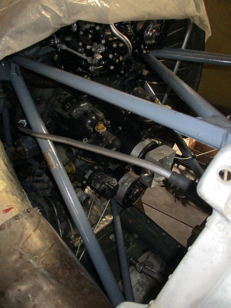 The other engine also had a reducer in situ but no way would it budge so the further level of removal took place (after considerable mumble grumble) and that's off for during the week attention. Then moving onto feeds from the engines to the cockpit gauges for oil pressure. There are two tubes to make the connection on each engine, joined by a flexible coupling. Our friendly tubing tables called out dimensions for the second tube on the port as having bend 1, 2, 3, 5 but nothing for bend 4. So then a piece of to-hand welding rod was inserted into the firewall union of intent and marked where bend 5 would be and I worked out what bend 4 should be. So after a further bit of adjustment here the tube runs ... 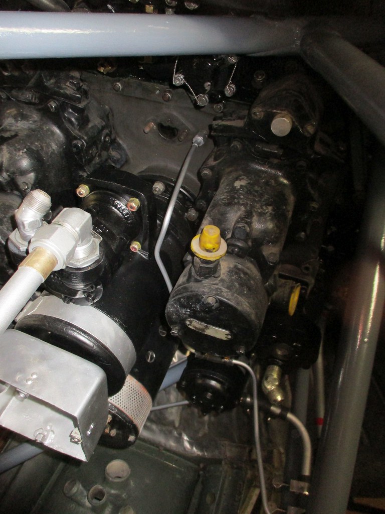 Off the rear of the engine case we go to the aircraft rear and then duck off and under the magneto and out towards the the edge of the nacelle before turning .... and following the member of the engine frame and then turning again and making our connection to the firewall. 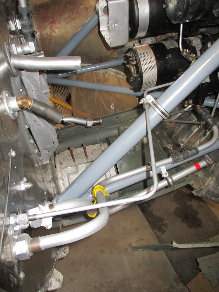 Then we worked the whole scenario again on the starboard side but different as this side has to cross underneath the engine towards its left side rather than sliding down the right....amazing where the day went after I finished up with some clean and prep on some structure stuff! ttfn |
|
|
|
Post by ZacYates on Mar 20, 2022 8:52:29 GMT 12
As I say on the various modelling forums: any progress is good progress! Thanks for sharing Denys, I may not always comment but I read and enjoy each update.
|
|
|
|
Post by Antonio on Mar 20, 2022 9:46:15 GMT 12
As I say on the various modelling forums: any progress is good progress! Thanks for sharing Denys, I may not always comment but I read and enjoy each update. Ditto |
|
|
|
Post by camtech on Mar 20, 2022 11:51:30 GMT 12
One of the conundrums of the week concerns the suction gauge feed to the instrument panel. This is, path of which aside, why is there only a feed from the starboard engine?
Been thinking about this and can recall this issue with an aircraft I've worked on during my air force career. Did the Hudson have a vacuum pump on both engines? Could be common to other aircraft? I know it does not sound logical, but aircraft designers sometimes have weird ideas about these things.
|
|
|
|
Post by denysjones on Mar 20, 2022 14:22:27 GMT 12
There is a pump on each engine that's what puzzles me so about it,
|
|
|
|
Post by oj on Mar 20, 2022 19:29:24 GMT 12
Good stuff, but what about my generator question?
|
|
|
|
Post by denysjones on Mar 21, 2022 8:26:51 GMT 12
I PM'ed you that the Parts Book calls out as a Type O-1 but based on visuals and what I've come across locally I've installed Eclipse 314's but have no idea of the electrical specs. :-)
|
|
|
|
Post by curtiss on Mar 21, 2022 12:23:04 GMT 12
Type O-1: Used on 24 Volt systems. Generates 28 to 30 Volts. 100 Amps, 2500 to 4500 RPM, Counterclockwise rotation, Mount flange round with 12 holes. 16 spline shaft.
Eclipse 314: ( type M1 ) Used on 24 Volt systems, Generates 28 to 30 Volts, 50 Amps, 2600 to 4000 RPM Counterclockwise rotation, Mount flange round with 12 holes. 16 spline shaft.
|
|