|
|
Post by Dave Homewood on Mar 21, 2022 13:33:09 GMT 12
|
|
|
|
Post by ZacYates on Mar 21, 2022 15:55:21 GMT 12
That's fantastic Dave, thanks so much for alerting us! Very useful for the modellers among us, especially anyone (*waves*) planning a build of '013 herself. |
|
|
|
Post by denysjones on Mar 21, 2022 17:48:20 GMT 12
That's interesting stuff thanks Mike.
I remembered that I'd settled on the Eclipse 314 based on a some reference I'd come across and so went back to a page of the Erection & Maintenance manual called "Engine accessory chart" and sure enough that's clear on it being the Eclipse 314 with no mention of the either the M-1 or O-1 type designation.
The copy I had used as a reference was T.O. 01-75AB-2 dated December 1943 and lent to me many years ago by Charles Darby. Since then I've acquired a later 01-75KA-2 digital version which sadly is missing the first few pages so I don't have a date for it. However looking at that the corresponding chart now does not call out a manufacturer specific model number but uses the O-1 and refers to it being either a Delco-Remy or Gen. Elect.
Given that the difference between the two types, you so kindly spelt out, is amperage I'd guess that with the addition of more electrics as the war progressed they switched types to get the current needed.
|
|
|
|
Post by curtiss on Mar 22, 2022 11:25:27 GMT 12
Denys, Check your emails. I have sent you the electrical manual I got the data from.
|
|
|
|
Post by Dave Homewood on Mar 27, 2022 19:18:44 GMT 12
I just happened across this letter to the editor of The Press dated 5th of August 1971.... Preserving relicsSir, —I should like to express my sympathy for Mr Norris and die problems facing him with regard to relics and the public attitude to them. Many people speak out for the preservation of such items, but just as many want to make a dollar out of the same items. It is deplorable how many members of our farming community, who have a lot of aviation relics on their properties, prefer to try to raise comparatively large sums of money from voluntary societies such as ours for items which need !careful restoration and combination with parts from other sources to make a finished exhibit. Since the societies cannot afford these sums the items are left to rot and then are gone forever. The action of a local man in buying such items for sale to our American friends also does nothing to alleviate the trying situation. It is about time a lot of New Zealanders got their priorities right with regard to money and historic items.— Yours, etc., DENYS JONES, Ferrymead Aeronautical Society. August 3, 1971. paperspast.natlib.govt.nz/newspapers/CHP19710805.2.92.3 |
|
|
|
Post by Dave Homewood on Mar 27, 2022 19:20:24 GMT 12
Over 50 years of voluntarily working to rescue and preserve and make available our aviation heritage, well done Denys! You deserve a gong!
|
|
|
|
Post by agile on Mar 27, 2022 21:13:29 GMT 12
Firstly, hear hear to Dave's comment above. Sorry I know we're well overdue an update on all things Wooden Wonder, time isn't my friend at the moment. We haven't been idle although there have been lots of disruptions. The repairs to the nose are going in the right direction. On the port side we installed a patch over the outside of the big crack in the inner skin and renewed the broken machine gun door sill and rotten hinge mounting block: 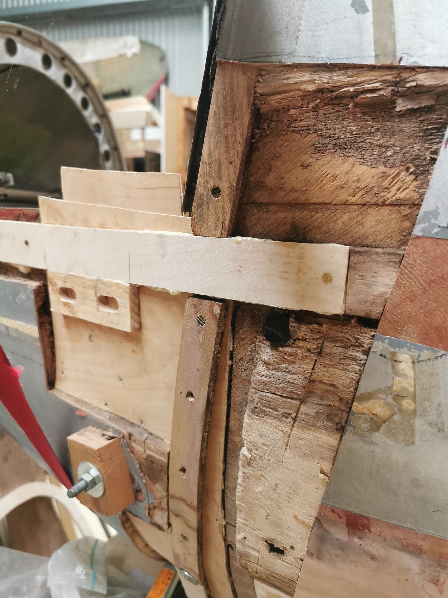  and we've now mostly filled the balsa back in.  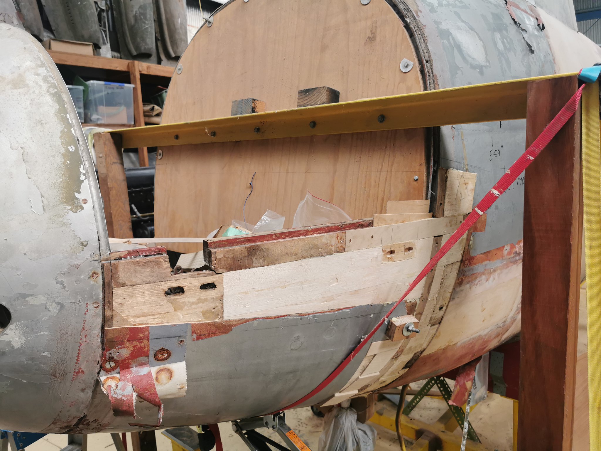 Now we just have to do the usual feathering of the edges and cut and glue the two missing bits of outer skin (one across the length of the repair, and a second one around the fuselage. On the starboard side the remains of the door sill (which had mostly been cut away prior to us getting the aircraft) have been removed back to the opening for the navigator's drift sight:  And Dagy has carefully laminated up a new sill and forward hinge block:   A few bits of veneer needing gluing back down there too! One of my other jobs in the meantime, in the scheme of bringing the aircraft back to wartime trim was to provide a mounting for the navigator's oxygen regulator. The wartime aircraft had separate Mk VIIIB regulators for pilot and navigator, with the pilot's mounted in the instrument panel and the navigator's beside/behind the pilot's seat (#30 in this diagram from AP2019E).  All of the aircraft that came to NZ would likely have been modified to a single Mk XI regulator in the instrument panel - NZ2328 certainly was, as was TE910. The panel where the regulator along with the main oxygen valve mounts is attached to the underside of the navigator's bench - you can see the panel with the oxygen valve in place in the middle of this pic of TE910 borrowed from their FB page:  I used a piece of Hudson from a certain scrap pile at Mapua as a pattern: 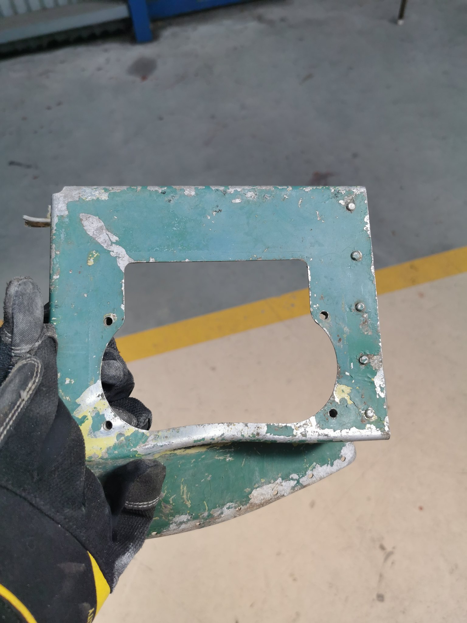 To make a new panel, rather than chopping up the original which we can retain:  This has now been finished and sent off for painting. Speaking of TE910, yesterday I happened to find myself staring at our spare Junction Box C (which we think is from HR339 judging by the date 25 May 1944 scratched into the back). It occurred to me that we never looked to see whether there was a 'maker's name' on this one as there has been on each of the others we have seen ('Eileen' on NZ2328, and 'Laura' on the spare box we got in a parts trade a couple of years back). Turns out it's a small world....  (In case anyone missed it at the time, here is the connection: rnzaf.proboards.com/post/290149/thread)Cheers A |
|
|
|
Post by ZacYates on Mar 28, 2022 12:15:31 GMT 12
Excellent update Alex! Thanks a lot for sharing.
|
|
|
|
Post by denysjones on Apr 2, 2022 19:29:37 GMT 12
It's been two more Saturdays in the world of Hudson engine tubing. Having previously plumbed up the inlet, outlet, and drain of the fuel pumps, that left one connection, the pressure equaliser, that runs up to the body of the carburettor which came up to be next to deal to. Looking at this illustration from the parts book the pump is down at the bottom and said pipe, labelled as number 4, runs pretty much dead vertical up to the carb.  Then the question arose as to which of two possible connections, closely spaced thereabouts on the carb body, it should hook onto but fortunately luck was with me as the tube bending tables had an entry for this tube. Once bent up and offered up to the potential locations, and with a bit of figuring out its relation to the engine frame and which end of it was the top, the conundrum was solved. 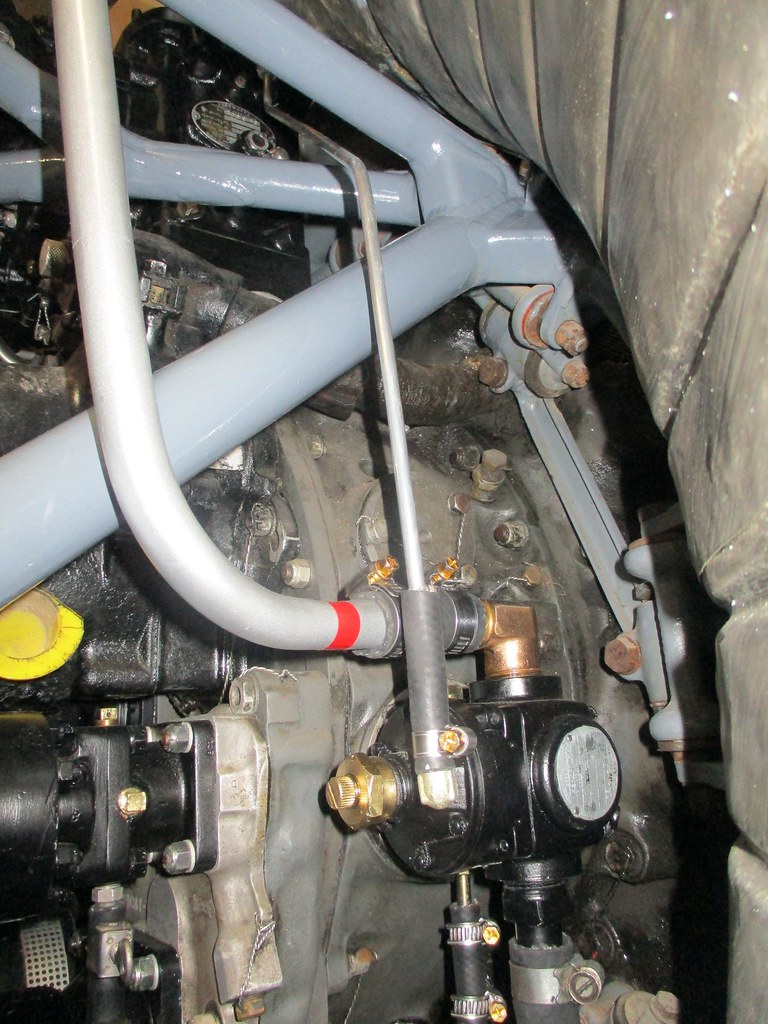 Last week I distracted Dag from mossie work to do some turning on the lathe for me, a dark art that secondary school metalwork back in 1965 doesn't cover, to turn down some bar for the manufacture of the remaining connectors for the firewall manifolds which was a weektime job. Now with all of them in place it's time to do the connections for engine manifold pressure, fuel pressure, anti-icing, and fuel priming, to finish off the block of six connections where the oil pressure ones are already in place. So this afternoon a couple of hours of contemplation and fabrication dealt to some more which are off to be painted this week prior to installation. Easy consumption of nearly 3metres of tube!  The bottom two are the two pressure equaliser ones. Seeing the first fitted making the second was a breeze because as it is the same engine and fuel pump on both sides of the aircraft and the pump is attached to the body of the engine of course they're the same. Next I hit the manifold pressure lines, these quite closely follow the oil pressure ones that are already in place that simplified making them as there's no call out for them in the tube tables hence they are improvised. The top two are the two halves of the line for the starboard engine and the remaining one is for the port, its other half will come next week. The fuel pressure ones are the next target being the set of four lines in the parts book diagram above....happy days are ahead of me! |
|
|
|
Post by denysjones on Apr 9, 2022 20:42:12 GMT 12
Another day of tube bending but there's only so many pictures of this and that tube that enthrall. However I had the idea that there might be interest in how it all happens based on the fact that one of the overall site team came over to have a look at my work and was most intrigued so, whatever, here we go. From the parts book I can obtain the part numbers of the specific tubes and from there I refer to the tube bending tables, in the erection and maintenance manual, where the tables are divided up into sections per plumbing system, oil, fuel etc, to locate the call out for said tube. It's something like a 50-50 chance then that the part number I have actually appears in the table, e.g. today I found one of a line of three, but when it does the entry for it will look like this one.  Each line has several "zones" of columns to it. At the start are things like the tube length, material type, and diameter. Then it introduces "End A" as a reference which is up to you to select physically on your piece of tube and then stick with that nomination because entries further on refer to End A, especially a column which calls out the type of connection that end is to have made on it. These can be C, for flare and nut type to go on plumbing fittings, or F, for flare or bead to go with clamped rubber joints. Another column at the far right of the table line specifies the other end's type of connection. It details a length of the specified size of tube, but longer I cut more than the length given as in the preface to the tables Lockheed specify to cut the length 10% greater than specified if making a replacement tube. Next there are blocks of five columns for each bend to be made. We'll concentrate on the first three columns in each of these, for reasons that will become explained later. Starting at End A we measure off the distances called out in the first column of each block and mark the positions on the tube. You'll see that the first mark is the furtherest away from A and the others progressively retreat back to it. Having placed all the marks (some entries in the tables extend to two lines if they have more than four bends) bending time comes. First just for illustration for those who have never seen one here's a bender, this being my handheld job for small diameter tube such as the 1/4inch stuff for the lines like fuel pressure. A fine wee beast purchased for a mere $32 from your local branch of Tool Shed.  We start by installing the tube in the bender with the mark for bend one lined up with the 00 mark on the bender and then form the bend for the number of degrees called out in the second column, 57 in our example above. Now we slide the tube forward to line the mark for bend two at the 00. When doing this care has to be taken not to allow the tube to roll so the centre top line of it stays exactly as that because now any entry in the third column comes into play, that is 152L for our sample. This is saying that before forming the bend we have to rotate the tube 152 degrees left (anti-clockwise), as you would see things if you look down the tube end on. And so we work on until all our bends have been formed. The fourth column in each bend block had me lost for a while until I found out about benders with a dial and marker to record the cumulative rotation of the tube. The dial and marker are zeroed before bend 1 and on the dial 0 is of course also 360 (degrees). So if you rotate the tube say 35 to the right the dial will end up with the marker having (360 -35) = 325 positioned against it. A further 40 to the right yields 285 and if we then went 60 left it would read 345. The fifth column in each block specifies the bend radius but my bender has but one, determined by the casting we're forming around, so I ignore that figure. You also can see the degree of finesse in the graduations for forming bends on my bender is such that there is no way I can be precise to single degree measures and even less so estimating rotations of a tube of 1/4inch diameter. So I proceed to test fit the product and go through a process of adjustments, to compensate for the effect of columns four and five, until an acceptable fit is reached. Hopefully some of you viewers have found this of interest...cheers |
|
|
|
Post by curtiss on Apr 10, 2022 8:08:49 GMT 12
I wish all aircraft had this information available.
|
|
|
|
Post by davidd on Apr 10, 2022 14:36:43 GMT 12
I think you may just be a type of modern pioneer in having to learn the archaic art of tube bending in three dimensions Denys - well done! Must keep the old grey cells ticking over under the cranium. Then again, I guess modern aircraft (and other types of machinery) still have a lot of fancy tubes for various systems, with perhaps most items already preformed at the factory in a jig? I did find your descriptions moderately interesting too. I notice that modern cars are usually fitted with various types of flexible synthetic rubber hoses for braking and cooling systems, etc, usually molded exquisitely into very attractive units (and costed accordingly no doubt).
|
|
|
|
Post by denysjones on Apr 19, 2022 9:32:10 GMT 12
Time to take you back to January 18th's post and the two solenoids we had received.  By way of a post on the Flypast forum I'm now satisfied that they are from Boulton & Paul Type C turrets from Hudsons and so that ticks off another item from the wants list. The first one tidied up nicely so I'll next hit it's mate and then I just need the Brownings to hang them on....anyone got a pair in their shed? 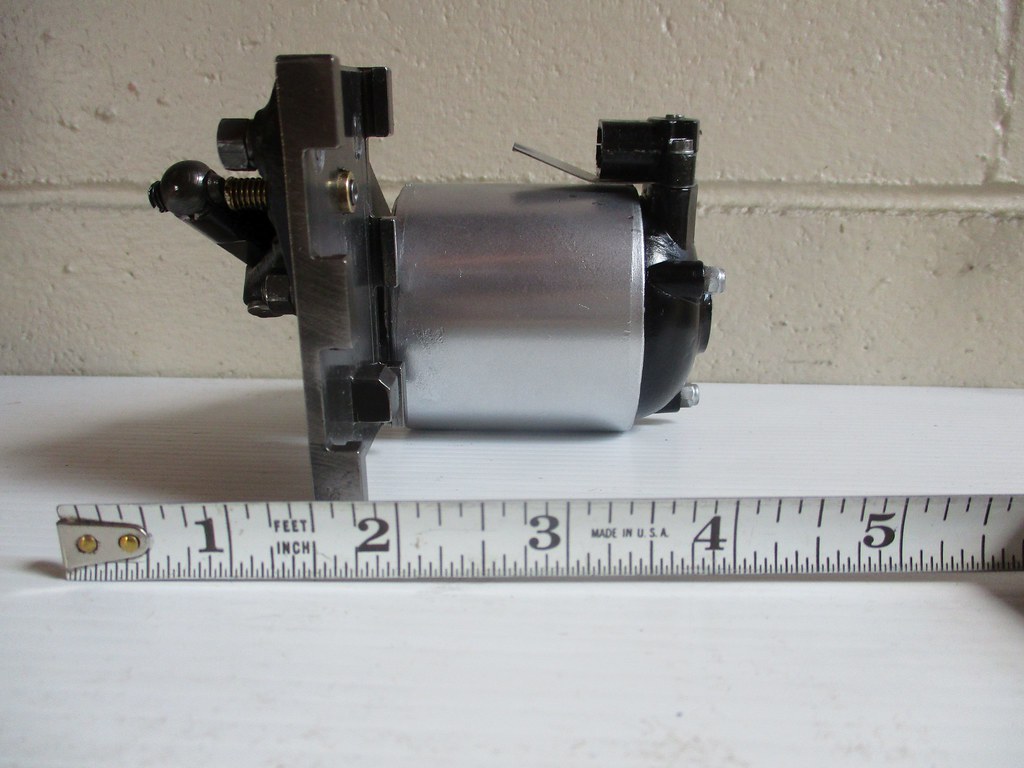 You can read the whole thread if you want on the Flypast forum at www.key.aero/node/170562ttfn |
|
|
|
Post by ZacYates on Apr 21, 2022 14:09:57 GMT 12
What a stunning result! And's it's nice to see not all those with valuable knowledge jumped the Key ship after the forum re-do.
|
|
|
|
Post by denysjones on Apr 23, 2022 21:24:56 GMT 12
Just a wee bit more of tube land but last weekend I had a visit from Chris McDell (Cyclone restorer and Rukuhia excavator of hereon) who brought me a wee treasure of his diggings namely..  What beit I hear you say? Well it is part of this  which is the gust lock/control lock for the Hudson. It is obviously not the most likely useful thing from the great disposal days but Chris came upon it in his diggings and so we can salvage the two castings off it and work from there. With some luck he might be able to find the other half, specifically the casting that latches onto the control wheel, nearby the original find point. While I've got your attention...anyone out there have a control wheel of the same? Some thieving sod stole the one from 2035 while she sat at Woodbourne awaiting the C130 to Christchurch. cheers |
|
|
|
Post by ZacYates on Apr 24, 2022 9:05:20 GMT 12
The control lock - very cool. Theft of the wheel way back when - not cool!
|
|
|
|
Post by agile on Apr 25, 2022 8:37:28 GMT 12
On a happier control wheel related note, a forumite recently dropped in a Sunderland control wheel for the cockpit of NZ4112, which was gratefully received.
|
|
|
|
Post by denysjones on May 14, 2022 20:46:24 GMT 12
Another couple of weeks of merrily tube forming have just passed by since last report, as the on-site side of life. On the home workshop side the first task of the week was making up replacement supports for the assorted tubes as they run across the forward face of the centre section between the fuselage and the engine nacelle. They are rubber plates liberally peppered with holes of various sizes for the diameters of the tubes. Groups of these holes are arrayed around the bounds of rectangular holes large enough for the connection nuts of the tube ends to pass through. We had the remains of the two originals each damaged but fortunately between the two there was enough to figure out the whole. So here on the left is one of the originals and a replacement which still needs some work on the cluster of five holes at the bottom.  Next I salvaged the fittings from the control gust lock received the other week. The remains of the tube simply fell apart on the floor at the mere hint of pressure, apart from the pieces inside the fittings which came out amazingly tubelike. While cleaning the fittings up I kept on having thoughts that one in particular just seemed so familiar. Therefore on Saturday I rummaged through the workshop shelves and found out why...I already had part of such a lock namely the end that secures to the pilot's control pedestal. This had come our way a couple of years back and been duly bagged and tagged and put away for a day in the future which has now come. So things have now progressed to being thus, at the left the end to attach to the control pedestal and to the right the half we have of the clamp that grips the control wheel.  We also have a duplicate item in the foreground which is from the latest treasure Chris provided the other week. Interestingly it looks identical to its counterpart above it but it has a different P/N while the two on the tube have the same P/N despite each having had holes drilled in them for different purposes which now makes them distinctly different. That non-change of P/N after customising for specific use seems a tad non-Lockheed in some ways if you follow me. Just a couple of bits to go with that left pair and then to find the buddy of the control wheel grip piece and we'll have a complete lock. |
|
|
|
Post by Dave Homewood on May 14, 2022 21:08:52 GMT 12
Great stuff!
|
|
|
|
Post by agile on May 15, 2022 9:27:27 GMT 12
Down in the land of glue and sawdust, the repair to the earthquake damage on the port side of the nose has been re-skinned: 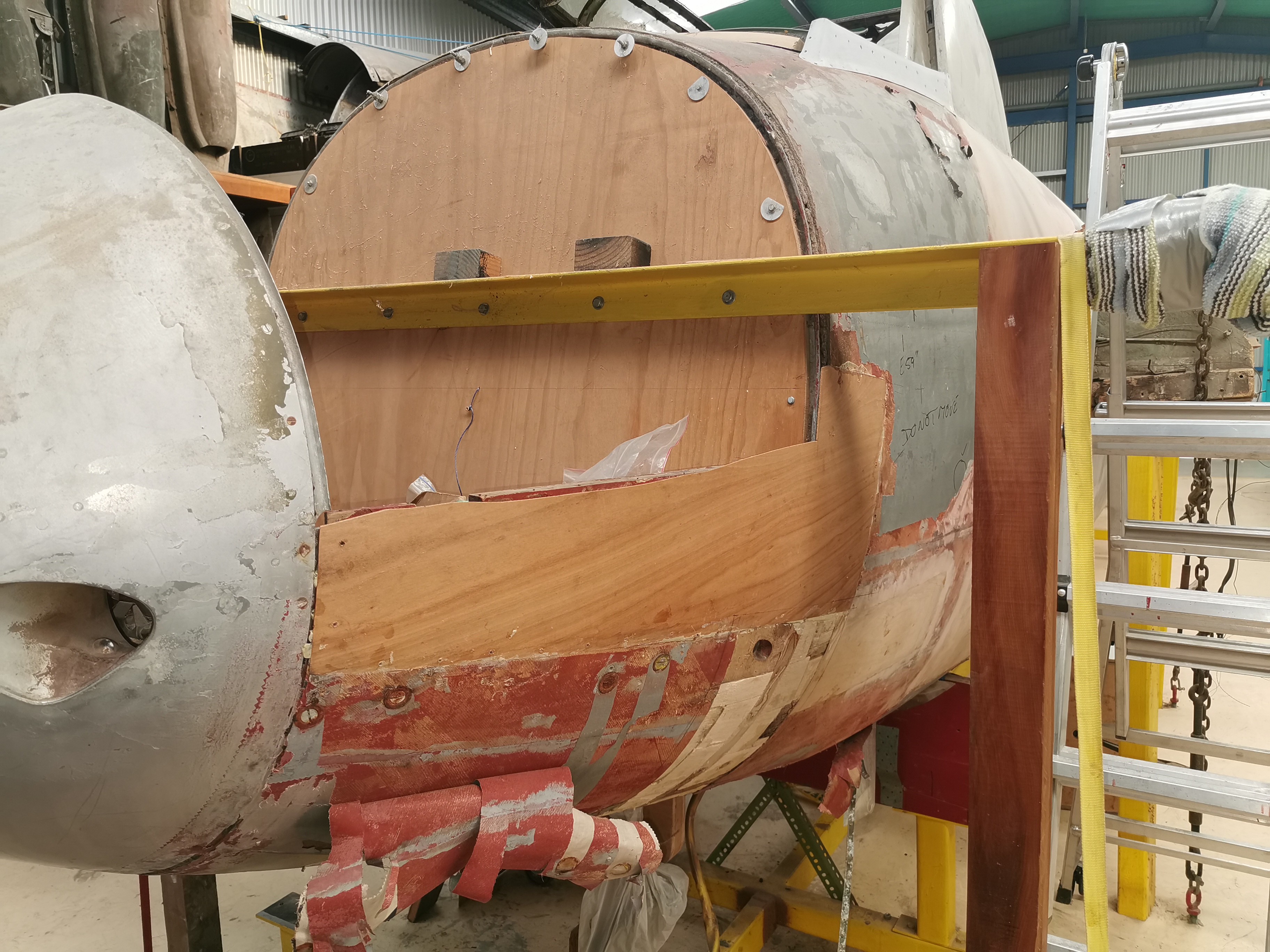 The top piece of skin was relatively straightforward, the bottom one, which incorporated a fair bit of compound curvature took a bit more persuading (messers de Havilland, Powell etc solved this problem by applying the outer skin in this area in narrow strips, which we'll do on the other side but which obviously wasn't an option here):  The end result looks pretty good to us though:  In between building a new house, working full time and having knee surgery, Dagy has found time to finish off a couple of new 20mm feed chutes. They're a tricky piece of sheetmetal fabrication but no problem for the master (guess which is the genuine article out of these three):  George and his team of young minions have been working on our engine cowl disks. We got two of these from Avspecs as a trade a few years ago. Both were heavily corroded and one was denuded of its steel fittings. As luck would have it, I found a damaged but complete one on the scrap pile at Mapua, so George and his team have been hard at work de-rivetting and decorroding, filling, painting and re-rivetting. This is an example of the state they were in - lots of electron swapping action going on here:  George is a brilliant tutor, overcoming his challenges with English (he arrived in NZ with, in his own words "156 words in my tool kit", but he has come a long way since then) and is a huge asset to the team:  And is very patiently getting these lads (Reed and Oscar, who are both dedicated volunteers) to the point where they are undertaking fairly complex tasks on their own (under his slightly anxious supervision):  Down at Electric Avenue Angus is working his way through the cockpit wiring, restoring sun damaged and perished cables so that they are ready to fit straight back into the cockpit. Here he has the wiring for the Type F signalling equipment on the starboard side of the cockpit laid out:  For my part, we have a growing list of cast parts we need to get made as I have struck out in attempts to acquire originals through trades. To this end I have been modelling up some of the offending articles in CAD so we can 3D print patterns. Here is the elevator pulley bracket from the tailplane:  And the torque link from the elevator trim mechanism:  My respect for the pattern makers of old has grown immensely over the course of this exercise, especially when you note some of the madder details of these parts. The flanges of the bracket are tilted 1.5 degrees to one side, and the torque link has a flair that changes radius as it goes around the tube. All good fun stuff, and well and truly keeping us off the streets! Cheers A |
|