|
|
Post by denysjones on Jul 8, 2023 21:04:42 GMT 12
A very small team on site today due to the weather but that's life, apart from the scrubbing of the Illuminate festival at the Park and the obvious income!. The last couple of week's homework has been small bits and pieces and today the refurbed control stick got installed in the turret, fancy a game of Space Invaders ChrisM :-)?  That was the easy bit. Then quite a bit of time was spent figuring a route, hopefully the right one, for the two electrical wires that form the firing circuit and the inner of what will eventually turn into a Bowden cable, the bar metal wire running downwards right to left in shot, that runs to an "armature switch", whose function I have yet to ascertain! From various manual illustrations/diagrams I know where the assorted bits bobs are in the turret but the routes to them are a mystery so it was a try this and then that experimentation. The slightly added complication was that the table hinges at the left side, to aid gunner entry/exit , and so each idea had to be tested for motion and position. After that it was the makeup of a shield that attached to the bare metal angle, to be seen under the table left side, which covers the rods, linkages, and wires under the table for safety of them and the gunner I guess. From the photos from manuals and assorted other real world turrets I've seen a variety of styles so today took the road of compromise of style and did my apprenticeship on our roller bender! The result seems fine to me so off we go with it. cheers |
|
|
|
Post by denysjones on Jul 15, 2023 21:15:24 GMT 12
During the week the shield that I rolled up last week was fine adjusted in terms of the tightness of the curvature and the holes for its attachment drilled and then another funny emerged. This is a clip from the best drawing I have of said shield, this being from the parts book  and you see the three holes in the front upper edge, which match those seen in last week's photo showing the attachment point, and the two holes on the rear, along with depictions of the attachments they marry up to. There's just a wee problem in that our turret's table doesn't have an attachment at either end on the rear but rather two closely paired in the right hand half. Also on the drawing there is a funnel shaped form on the front, near the leftmost hole, which lines up with an inverted U-shaped cutout in the attachment bracket. However none of the turret photos I have has that but rather just simply a hole and not even with a grommet, which I'm sure one would have been used given the numbers of them found everywhere else. So perhaps the differences are down to a later mark or mods or what...who knows! Never mind we'll run with the physical we have and decisions made from that so here she be, with just the wiring connections to be finalised. 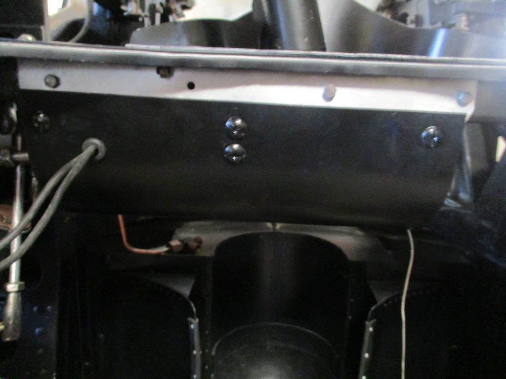 The other item completed was the latch unit from the other week and so here it is posed as it would be when holding an ammo can in place. I couldn't pose it with a can in situ due to the confines of the support the turret is resting in but imagine said to be projecting out to meet the upright portion and the gooseneck extends upwards to engage the latch onto the end of the can.  cheers |
|
|
|
Post by agile on Jul 21, 2023 10:08:02 GMT 12
Having said my piece on the NZ2423 thread it would be remiss not to update my fellow non-Facebook users on progress in Mossie-land. It's been a busy couple of months. Following on from the last update, the UV lamp exciter button bracket has been painted and Angus has been working on restoring the lamps:  He has also been installing the supply wiring for the system, which has been tedious but not especially photogenic! George and Oscar have finished assembling the first aileron, much to their evident relief:  In the meantime we removed the skin off our spare aileron, which was not in especially flash condition and had been a happy home for generations of rattuses: 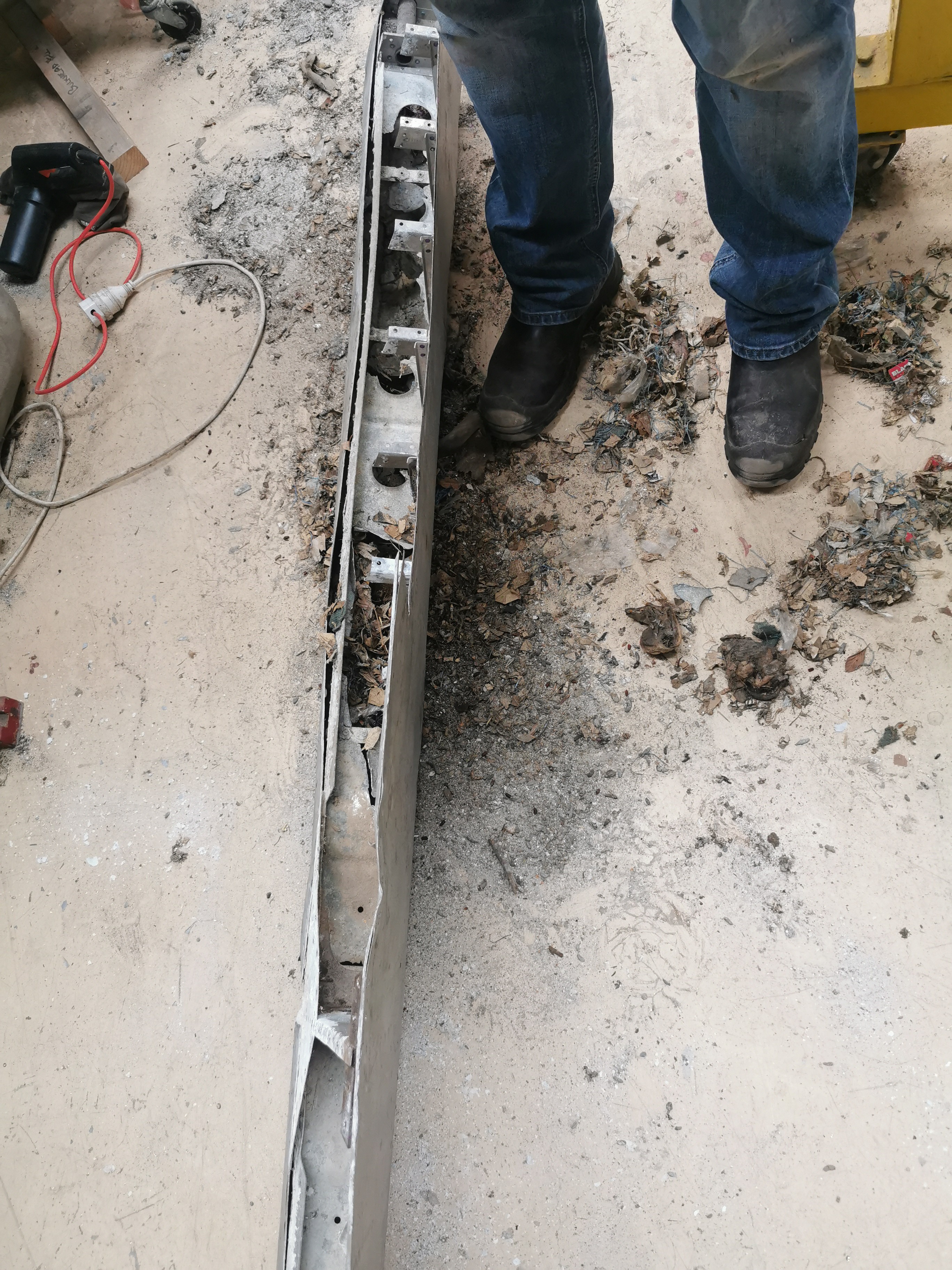 Dagy and I are hard taskmasters and so George and his lads were immediately set to work on aileron number 2, featuring a skin salvaged from the one in the previous pic (on the left in the photo below): 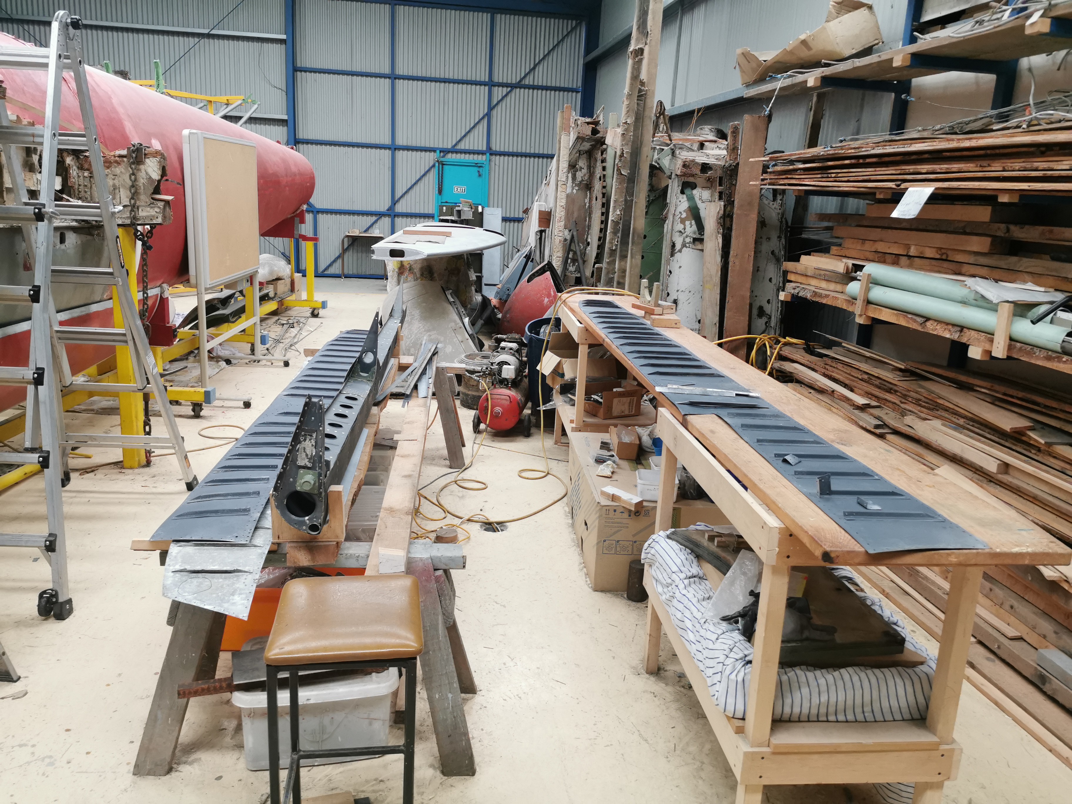 They're making good progress, and no doubt they'll have this one buttoned up in a few weekend's time:  In the meantime Dagy and I made the fuselage into a convertible by removing the canopy:  It turned out there hadn't been a lot left holding it on:  A complete set of mounting hardware for the canopy has been made/restored/found. It's amazing where even these tiny bits turn up from - three of the silver parts with the tag attached in the pic below came from a box from our mission to Auckland a couple of years ago - our originals were completely rusted away, so I just had to make one to complete the set of 4:  Under the canopy another classic bodge was revealed - this wedge of ply tacked under the canopy to fill in a gap: 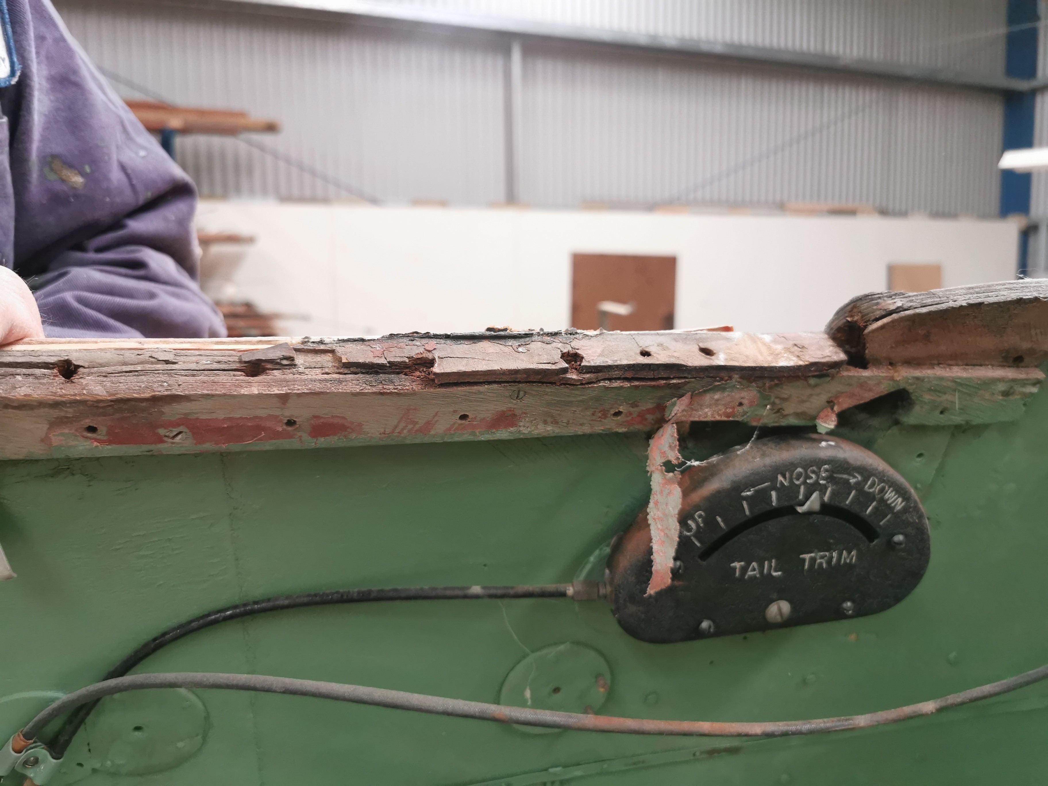 The original woodwork on the port side was in a bit of a sorry way: 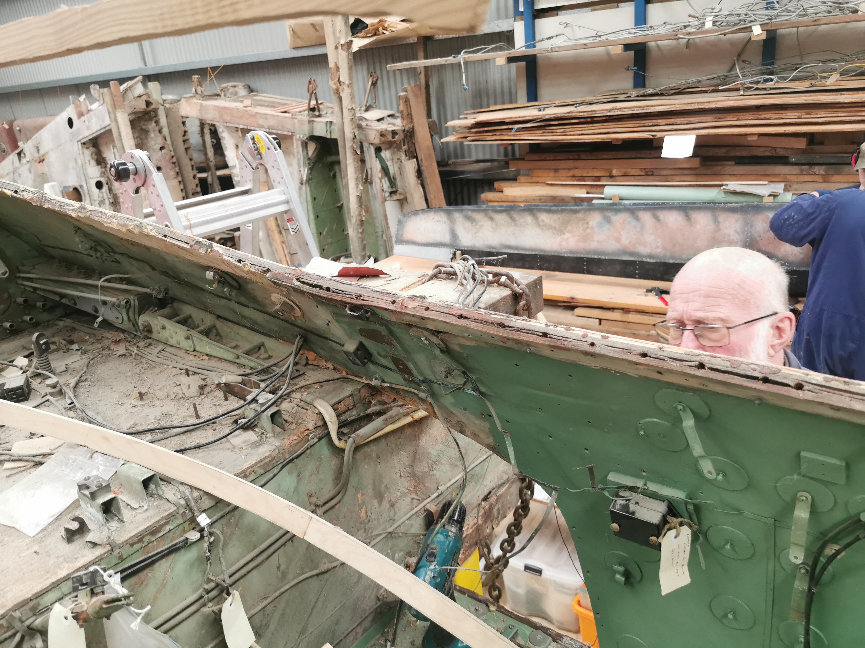 I had to cut away part of the wooden former betwen the two skins and splice in a new length (this is looking down on the edge of the fuselage shell):  Then replace the inner skin:  Dagy made up a nice curved laminated plywood doubler to replace the original, which I glued and screwed in place. I also replaced a few of the circular 'ferrules' used to mount components on the inside of the fuselage:  A bit of trimming and fabric over the top, and no one will ever know! Dagy has been working on the fuselage end ribs, which are the structure which form the inboard mountings for the radiators, and convert the curve of the fuselage to a vertical surface. He's had to make a lot based on drawings and minimal remains:  We'll only install the curved sections that attached to the fuselage shell for now, these will have to be trimmed back to fit when we have a wing with some radiators:   Friend of the project and forumite Robb has been a frequent visitor of late. One of the things he has been working on is getting gunsight brackets cast. These are based on a 3d printed model his son made from the original drawing. Said drawing is a bloody nightmare, and he has done incredibly well. The brackets now just need to be machined:  Rob was also keen to help disassemble the canopy, so he could take measurements to make one for his simulator project ( seen here) The first step was removing the sliding DV windows. Turns out there are quite a few bits in one window!  This is one restored original, and a NOS one which I believe a Mr Galbraith of this parish turned up from somewhere years ago:  Eventually the entire, rather sad looking canopy was completely apart. We're looking at getting the frame commercially soda blasted:  Dagy has also been working on restoring bits and pieces from the wings. Yet another bodge was uncovered on an inboard flap hinge. The star shaped piece of fabric:  Not especially successfully covering up a bonus drill hole - whoops!  Two nicely restored flap hinges duly re-appeared:  Finally, we've had the next lot of cockpit placards printed (at a generous discount) by the good folks at Allprint. These are printed on the reverse of clear PVC to mimic the originals which were water-slide transfers on celluloid. I did two sets of the radiator flap ones as we hadn't decided whether the blue colour was legit. It certainly seems like it from TE910 and the various examples at Avspecs. So weird:  I've installed a couple already, and my next mission for this morning is to do a few more:   Stay tuned (and be patient lol) for the next exciting update! Cheers A |
|
|
|
Post by ErrolC on Jul 21, 2023 10:47:00 GMT 12
Hi Ferrymead team, love your work!
We're planning a trip to Chch Sept/Oct (not school hols) to take in Ferrymead, Wigram and other stuff. What's the best day to visit for a look around? Saturday is when the workers are there?
|
|
|
|
Post by agile on Jul 21, 2023 15:23:50 GMT 12
Thanks Errol. Saturday is when the team are there, but I can be there other days by arrangement. Drop me a line at ferrymeadaero@gmail.com and I'll give you my number.
Cheers
|
|
|
|
Post by skyhawkdon on Jul 21, 2023 15:53:50 GMT 12
Great progress team.
|
|
|
|
Post by Antonio on Jul 21, 2023 18:39:53 GMT 12
"Having said my piece on the NZ2423 thread it would be remiss not to update my fellow non-Facebook users on progress in Mossie-land. It's been a busy couple of months." Thank you so much - I really appreciate that. Signed - Identifies as a non-social media person  |
|
|
|
Post by ZacYates on Jul 22, 2023 20:46:23 GMT 12
A fantastic update, I really enjoyed reading that! Great work by the team - I really like the idea of a homemade Mossie sim.
Now that I'm on the right island again I really, really need to revisit...it's only been 15yr...
|
|
|
|
Post by denysjones on Jul 22, 2023 21:25:51 GMT 12
While I was beavering away on things turret much elation broke forth from Harvardland as Team1058 reached a milestone point. Gerry and Barrie have been steadily working on the engine accessories, and engine accessory area overall, for some time and today attached the port side air duct and the lower cross member which supports the oil cooler. The latter posed a wee bit of a struggle but the guys got there. The air duct solved an issue with the firewall lacking the expected rigidity it now displays.  With the mounting of said cooler to be done next week that will see the major works in the bay over and a sight of beauty to behold it certainly is. Recent weeks have seen some of Dean's idle time coupled with his home workshop equipment. Armed with some blueprints of Lockheed origin he's turned out this, which as a subject line of the email reporting it's completion was termed "thing".  It is the actuating stay which elevates the forward edge of the Hudson bombaimer's "adjustable platform" aka "bench" in our speak. That's the Y-shaped unit whose fabrication you find on page 19 hereon but whose installation got sidelined by other matters arising. Dean reports that a G-clamp gave it's all in the interests of the fabrication. cheers |
|
|
|
Post by agile on Jul 23, 2023 10:13:26 GMT 12
A fantastic update, I really enjoyed reading that! Great work by the team - I really like the idea of a homemade Mossie sim. Now that I'm on the right island again I really, really need to revisit...it's only been 15yr... You really do! And when you come down we'll arrange a trip out to Rob's place to check out his simulator. |
|
|
|
Post by denysjones on Jul 29, 2023 21:46:02 GMT 12
Following on from Dean's work on the front screw-stay for the bombaimer's bench during the week I dug out the blueprints for the assorted other fittings and so set forth today to locate what is still in place in the aircraft and/or on the shelves of bits while Dean contemplated those items that I knew for sure we don't have and hence his machining projects they become. This task is the hinges on the rear end of the bench which obviously are required seeing the front end rises and falls on the screwjack. Dean dropped in armed with the four pages of blueprints to see what the whole thing was about. The bench projects into this tunnel/void which is below the centreline of the cockpit, as in it has the control pedestal above it and its rear wall is the forward wall of the bombbay. The view is looking aft and you can see topmost control cables from the pedestal heading aft to things like the rudders. There is a "ceiling" which attaches to the rising top angles on either side wall to keep things tidy.  Looking at the rear and above the lower cross member there are two protrusions visible on either side. These are fixtures bolted into the vertical member there and are the locators for hinge pivot pins for the aft end of the bench. After contorting himself so I could show him these, and muttering certain appropriate expletives about pain and the issues of the eventual installation, Dean and the blueprints headed off to do battle with material in the home workshop .... things will follow. My part in this began firstly with an overdue wipedown of the area (its a while since I was buried in here running said control cables) and the bending up of a pair of top hat members which will be fixed to the floor via the rows of holes you can see. These members are the supports for the anti-icing tank (see pages 30 & 32 hereon) which resides here and under the bench. Btw the circular cutout in the bench provides access to the filler of said tank. Next comes the fabrication of two restraining straps for the tank, and of course a repaint for the tunnel. When you see the short length of the tunnel and the bench (approx 50% of the latter for the former) it is clear that the appointees to the role of nav/bombaimer in Hudsons had to be of somewhat shorter stature. Another step in the game of acquisition of parts to complete the turret is now coming into focus and that is the actual armament. I've come across a firm in the UK (www.relics.org.uk) that makes a wide range of replica weaponery and one of their stock lines is a pair of Browning .303's but specifically the turret version of said. I'm no armourer but it seems sensible that as the turret guns get installed lying on their side then there could well be specific features to distinguish them. The units certainly look the part well enough for our purposes   The advantage of these offerings is that they are made of wood with no internal working parts, which gets around licensing issues, and so are lighter than the real guns. The rub is that a pair costs approx $1100, including shipping to NZ. So if you've got some spare cash and would like to help out you can do so via givealittle.co.nz/org/ferrymead-aeronautical-society just say that you want to support the Hudson turret guns. We can of course supply a tax certificate upon request. TIA. cheers |
|
|
|
Post by neil55 on Jul 30, 2023 9:20:19 GMT 12
|
|
|
|
Post by emron on Aug 2, 2023 16:49:07 GMT 12
Denys, the wooden guns illustrated above will not fit either the Frazer-Nash or the Boulton Paul turret without some modification. However they do have both front and rear brackets that would slot straight into the Mosquito mount. Here are details of the front Boulton Paul mount from MOTAT’s turret.  bp_front_mount bp_front_mount by Ron Wilson, on Flickr During installation on this mount, the pin is withdrawn from the square block and then the front of the receiver is lowered down over the block. the pin is inserted back through holes in the side plate of the receiver that line up with centre hole in the block. Next the rear bracket beneath the receiver is lowered into the rear mount and that pin pushed through the aligned holes.  bp_rear_mount bp_rear_mount by Ron Wilson, on Flickr To select a suitable version of replica you would need to ensure that it has the correct gap under the front of the receiver to accept the square block and that holes have been drilled in the side plates in line with it, so that the gun sits parallel in the mounting. |
|
|
|
Post by denysjones on Aug 5, 2023 21:17:19 GMT 12
A short day on site today for some reason.
In the morning Robbie, Dean and self were engaged in the installation of new box guttering on the northern face of the C47 hangar where the ravages of 20+ years saw the old stuff reduced to a red oxide lace curtain style..just more of the distractions of being a voluntary organisation.
Post lunch there was a marked evaporation of manpower due to something taking place in Dunedin but being rugby-averse I carried on and got the top hat sections, described last week, installed and after some final surface clean up, spot primed appropriate areas of the dreaded tunnel and first coated approx half the walls and floors hereof (shortage of space meaning it is a two piece job).
Ah well its just that some days see more visible progress than others :-)
|
|
|
|
Post by davidd on Aug 6, 2023 12:02:22 GMT 12
You're a real soldier Denys. Soldiering on.
|
|
|
|
Post by Mustang51 on Aug 6, 2023 14:42:23 GMT 12
Geez..even I watched the Bledisloe..........
|
|
|
|
Post by agile on Aug 6, 2023 19:38:12 GMT 12
Dagy and I both bunked off to watch it, but I'm not sure how engaged Dagy was - he WhatsApped me during the final minutes to ask about some bits what needed welding. Any excuse for an afternoon off, that's us in 633 Squadron.
|
|
|
|
Post by denysjones on Aug 12, 2023 21:39:10 GMT 12
Given the frigid temperatures of the day such tasks as painting things were well off the agenda! Dean and Rob finished the hangar gutter job connecting a Dean fabrication to it to link up with the down piping so that's that job all signed off. Team1058 did the couple of steps backward to one step forward routine when they encountered an alignment issue as they went to install the oil cooler. All this probably related to 1058's paddock landing and some forward distortions but at the end of the day the cooler is in and now they move forward again to replace the removals (note the portside air duct is now missing again).  I spent a frustrating time removing a small junction box that resides high on the port side wall of the tunnel. You can see it in the lower left of this old shot (good heavens a shot from year 2000!).  It's attachment disconnection involved some of these bits, the others are for the on-going attachments so to speak.  The union on the upper right goes through the tunnel wall with a retaining nut on the side of the tubing connection. Then the box fits over the left end against the nut portion and then another retaining nut secures that. The big trick was that both nuts and their threads were well seized and the nut on the union was inaccessible in terms of getting a spanner on it due to its thinness. Lots of CRC and small increments of swing with two large ring spanners, which I fortunately have courtesy of a donation by a local supporter years ago, it is all apart. Lady fortune smiled upon me and the right hand nut succumbed first and the whole unit came away and was easier to deal with on the workbench. Luckily the small number of visitors to the Park today meant few were likely to hear the crashes and bangs and bad language involved. A dive into the assorted bits box turned up the cover plate and the general stores supplied some washers which surprisingly were not present originally. This week, fair weather hopefully prevailing, the kitset will get dealt to in the home workshop and go back in next week. tfn |
|
|
|
Post by denysjones on Aug 19, 2023 21:14:54 GMT 12
This week while working on the recovered junction box I started to ponder the connections to be made to the two connectors on it that were previously not so endowed. My photos of other assorted Hudsons didn't yield any answers but Dave McDonald kindly undertook a lunch-time mission to photo-bomb the tunnel area in the Smith Hudson which is of course untouched since recovery from Mapua (and presumably since RNZAF disposal). As Dave said in his email to me it answered some questions and raised other new ones, for example this photo. 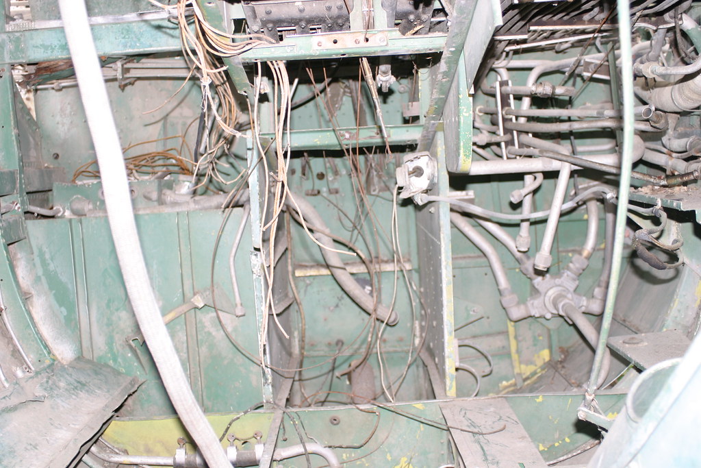 The major new one is that the junction box there has a hole in the back face with a grommet in it and two cables through the grommet which then swing out towards the starboard of the a/c. Our box has no such hole (and as a by-the-by therein I uncovered a P/N 76981-2 stamped at exactly that point in it, which as usual isn't in my parts book). Also shown is a largish diameter flexible mesh tube hanging loose in the tunnel area but deduction leads to it connecting to the starboard side of the box and, as shown, off to another box lurking beneath one of the steps down to the nose compartment. Also revealed was a support bracket and clamp, just visible behind the foreground vertical rod in the photo, for the port side tube to our box which I'd long assumed would have existed but had no idea/indication past that. Lastly in the front bottom cross member of the tunnel is a hole and grommet but in 2035 no such exists. I then contemplated the tank installation. In the blueprint I posted the other week the connector for the feed pipe from the tank is shown pointing left on the plan and running from it, forward in the a/c sense, the tube passes through a member, which looks to be like the one with the grommet in it above but on the port side of the a/c, before doing a right angle to attach to the pump. The tank as I received it has the connector 180 degrees out of phase with the diagram but it was firmly secure which suggested "as original". Both a/c have a suitably large hole at the bottom of the longitudinal wall of the tunnel immediately adjacent to the tank's connector which ties in with the blueprint location of the connector. Therefore as those all tie up that's the route we'll take. The blueprint shows a feed, of a small nature, off the pump which would appear to match the grommet absent in 2035 so that remains a puzzle for the moment. So first up today was to attend to matters in the now freshly painted tunnel, namely the refitting of the refurbished junction box and lines of felt along the bottom members which the tank will sit on. 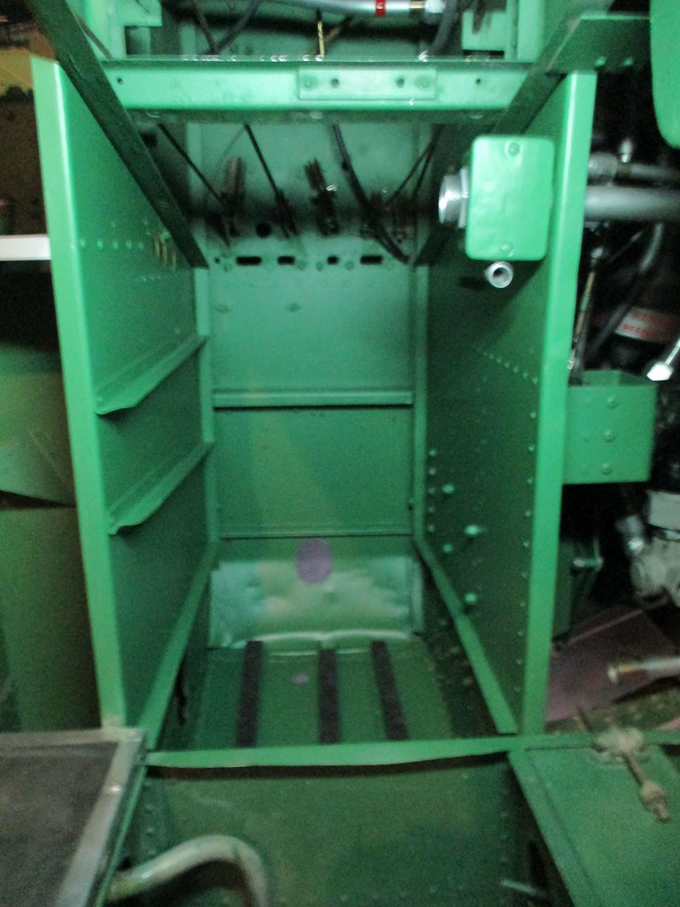 Next was to check items on the shelves which might be some of the cables Dave's photos revealed but as things so often turn out we didn't get a hit which led to sorting out components to make up new ones. The afternoon was dominated by making the retaining straps that will hold the tank in place and sorting out appropriate turnbuckles so the results of those labours can be finished over the week. More small progress but good to have it knocked off. To finish I removed the masking from the front half of the turret cupola which has had the final frame spray, covering the plethora of screw heads on the fixing strips. Now to do the reverse, namely the nuts, so it can move towards fitting in the next week or so.  |
|
|
|
Post by Antonio on Aug 20, 2023 10:02:31 GMT 12
Thank you so much for the weekly updates (another fix)
Really appreciate them, you guys are so committed to your aircraft
|
|