|
|
Post by johnnyfalcon on Feb 3, 2020 14:23:11 GMT 12
"Ah grasshopper, beginning of wisdom you show"
|
|
|
|
Post by planecrazy on Feb 3, 2020 17:27:21 GMT 12
So without sounding too bold and please tell me to go away if I am being so.
Would be grateful if you are willing to share some of your wisdom re how all
this is done, from what I can make out you make a wooden former from the
plan and bend the alloy over the wood? Do you make many mistakes and have
to go again, is the alloy quite thin do you heat and/or hammer the bends?
Looks like lots of sharp edges are you covered in cuts and have shares in a
band-aid factory?
by the looks there is a bit of soldering, are the gold coloured pieces brass or
copper, are the rivets glued on?
Again sorry if I am asking too much just find this fascinating!
|
|
|
|
Post by nzgrasshopper on Feb 3, 2020 23:10:10 GMT 12
All parts start off the same way. A plan is chosen from over 6000. Early on I went through all the drawings and found all that were for the P40N-5CU and up and placed them in sub folders.
The chosen plan is printed out and the longest dimension chosen. E.g. 17 5/8” = 17.625” x 25.4 = 447.675mm x .1666 (1:6 scale) = 74.58mm / 90mm (measured distance on the drawing) = 75.33%. Each plan is resized on a photocopier. Most plans only require a scaled copy. Some require a mirror copy as well. This is indicated on the plan as LH shown RH opposite.
The pieces are cut out and gluestick glued onto MDF in the case of the bulkheads or directly onto the aluminium. The glue dissolves in water afterwards.
Some parts require cut outs from the three or four views of the drawing. These are joined together in a flattened pattern and then bent to the correct shape afterwards.
The edges are scored with a Stanley knife and the rivet holes drilled. Larger holes are shaped using a chainsaw file. The excess parts are bent back and forth along the score line to give a clean break. Bends are made by placing the piece in a small vice with aluminium jaw guards to give a sharp edge. The aluminium is quite soft and can be bent over with your fingers. A flat edge is placed over the bend and given a few taps with a hammer to flatten it out.
The metal for the bulkheads is cut slightly over sized. The section that is to be shaped is scribbled on with a sharpie pen and then heated with a butane soldering iron flame until the marker disappears. The edges are able to be bent over with your fingers and then gently tapped with a small hammer. This work hardens the aluminium again. Sometimes a section may need reheating. Outside edges are easier to form than the inside curves, which can split.
If a piece is structural or needs to be a bit stiffer K&S 0.016” aluminium is used. The smaller parts and skins are made from 0.2mm aluminium sheets. Wing spars were made from 0.5mm aluminium sheet.
Only a few parts have needed to be made again. The original microfilm copies were not always that clear and the scanning to digital was not always that good. Very easy to mistake a 1 & 7, 3 & 8, 5 & 6, which throws the scaling factor out.
K & S brass tubing and shapes are used. They used to make a much wider range of products. I have managed to find some of this when visiting old hobby shops, where it is usually hidden in a corner gathering dust.
All rivets are used as structural connectors. Joining pieces are match drilled and the rivet pushed through. The tail is cut off and then set with a modified nail punch.
Just the occasional 1mm drill through my fat thumb when I misjudge the pressure required to drill a hole.
|
|
|
|
Post by nzgrasshopper on Feb 3, 2020 23:52:48 GMT 12
Wing sub ribs at station 81.5 between spar #3 and #5. This is where the ammo feed chutes pass through. 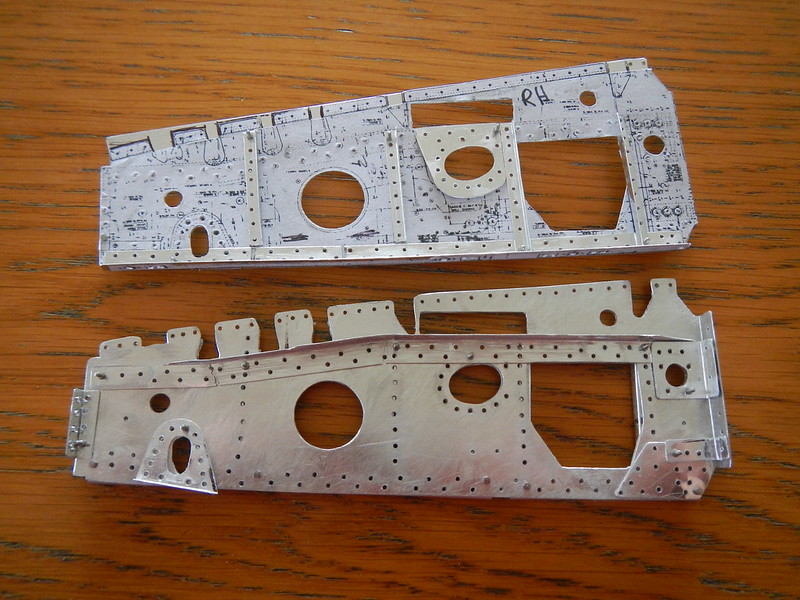  Sub ribs at station 27 between spar #2 and #3. The 2 on the right are either side of the main landing gear strut.  The hydraulic ram driving the main landing gear strut runs between this assembly  Sub ribs at station 27 between spar #3 and #4. Forms part of the inner wheel well structure. 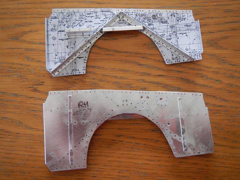  |
|
|
|
Post by nzgrasshopper on Feb 4, 2020 0:34:04 GMT 12
Oil tank cover panel and filler access panel  Doubler plate for fuselage fuel tank filler and hand grip   Assortment of pieces to be included into other assemblies. 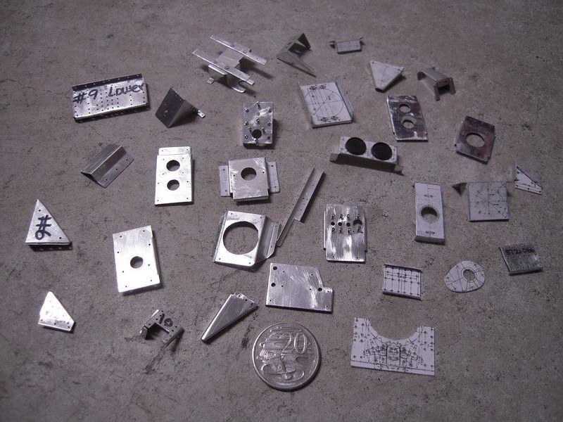 Trim wheel and cabin spot light holder  Instrument panel and main switch box  A lot more detailing to be done on this yet 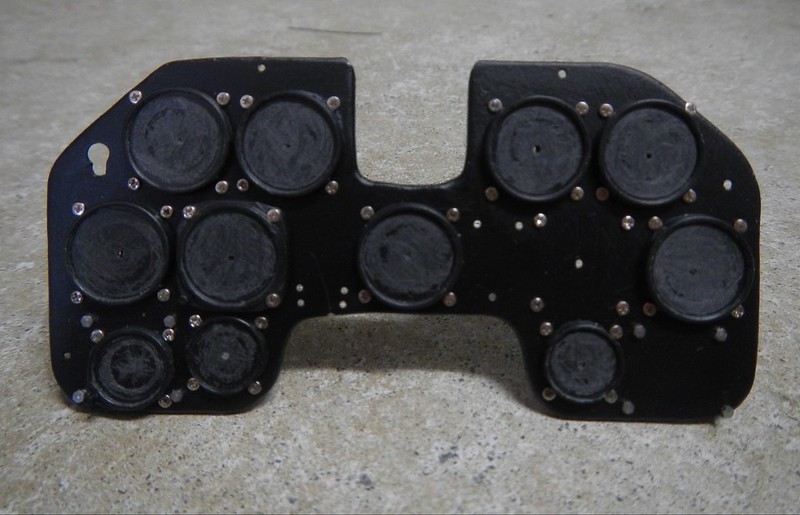 Wing doubler plates  Coloured signal light and white Morse code control box  |
|
|
|
Post by nzgrasshopper on Feb 4, 2020 0:41:16 GMT 12
A couple of my earlier efforts are in the Classic Wings hangar at Omaka. A kitset Corsair and a Wellington bomber.
|
|
|
|
Post by johnnyfalcon on Feb 4, 2020 6:38:49 GMT 12
Simply stunning!
|
|
|
|
Post by planecrazy on Feb 4, 2020 14:43:46 GMT 12
All parts start off the same way. A plan is chosen from over 6000. Early on I went through all the drawings and found all that were for the P40N-5CU and up and placed them in sub folders. The chosen plan is printed out and the longest dimension chosen. E.g. 17 5/8” = 17.625” x 25.4 = 447.675mm x .1666 (1:6 scale) = 74.58mm / 90mm (measured distance on the drawing) = 75.33%. Each plan is resized on a photocopier. Most plans only require a scaled copy. Some require a mirror copy as well. This is indicated on the plan as LH shown RH opposite. The pieces are cut out and gluestick glued onto MDF in the case of the bulkheads or directly onto the aluminium. The glue dissolves in water afterwards. Some parts require cut outs from the three or four views of the drawing. These are joined together in a flattened pattern and then bent to the correct shape afterwards. The edges are scored with a Stanley knife and the rivet holes drilled. Larger holes are shaped using a chainsaw file. The excess parts are bent back and forth along the score line to give a clean break. Bends are made by placing the piece in a small vice with aluminium jaw guards to give a sharp edge. The aluminium is quite soft and can be bent over with your fingers. A flat edge is placed over the bend and given a few taps with a hammer to flatten it out. The metal for the bulkheads is cut slightly over sized. The section that is to be shaped is scribbled on with a sharpie pen and then heated with a butane soldering iron flame until the marker disappears. The edges are able to be bent over with your fingers and then gently tapped with a small hammer. This work hardens the aluminium again. Sometimes a section may need reheating. Outside edges are easier to form than the inside curves, which can split. If a piece is structural or needs to be a bit stiffer K&S 0.016” aluminium is used. The smaller parts and skins are made from 0.2mm aluminium sheets. Wing spars were made from 0.5mm aluminium sheet. Only a few parts have needed to be made again. The original microfilm copies were not always that clear and the scanning to digital was not always that good. Very easy to mistake a 1 & 7, 3 & 8, 5 & 6, which throws the scaling factor out. K & S brass tubing and shapes are used. They used to make a much wider range of products. I have managed to find some of this when visiting old hobby shops, where it is usually hidden in a corner gathering dust. All rivets are used as structural connectors. Joining pieces are match drilled and the rivet pushed through. The tail is cut off and then set with a modified nail punch. Just the occasional 1mm drill through my fat thumb when I misjudge the pressure required to drill a hole. Thanks for this really interesting finding out what goes on behind the pictures, bewildering stuff! |
|
|
|
Post by agile on Feb 4, 2020 19:13:20 GMT 12
Extraordinary work!
|
|
|
|
Post by nzgrasshopper on Feb 4, 2020 23:23:33 GMT 12
Electrical BUS box   Starboard underwing gun access panel  Wing tank fuel selector mechanism  Signal pistol and holder.  Oil tank, bracket assembly and forward armour plate  |
|
|
|
Post by johnnyfalcon on Feb 5, 2020 4:24:49 GMT 12
...!!!
|
|
|
|
Post by nzgrasshopper on Feb 5, 2020 15:35:40 GMT 12
Starboard wing spars #1, #2, and #3. #2 and #3 have around 900 rivets each in them.  Wing jig  The hydraulic ram driving the main landing gear strut runs between this assembly  This is old mate, who will be doing acceptance flight trials when it is all finished  |
|
|
|
Post by planecrazy on Feb 5, 2020 15:38:40 GMT 12
Starboard wing spars #1, #2, and #3. #2 nad #3 have around 900 rivets each in them. if I got that right 4 X 900 rivets in four out of six spars, enough said, amazing! |
|
|
|
Post by nzgrasshopper on Feb 6, 2020 14:32:08 GMT 12
Port #2 spar trial fitting prior to riveting  Port wing. Trial fitting of sub ribs and #2 and #3 spars to the wing joiner  Port #2 spar and sub ribs 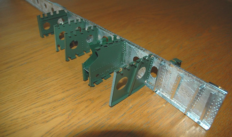  Current state of the port wing   Port underwing gun access panel  Port #4 spar  Port inboard wheel well sub rib  |
|
|
|
Post by saratoga on Feb 6, 2020 14:38:03 GMT 12
Old mate looks barely old enough to grow stuble, let alone fly a 1/6 P-40.
|
|
|
|
Post by nzgrasshopper on Feb 6, 2020 14:45:57 GMT 12
They were younger than him flying back in the '40's
|
|
|
|
Post by planecrazy on Feb 6, 2020 14:54:12 GMT 12
Jeez NZgrasshopper, the pace at which you are putting this together, do you sleep much!
|
|
|
|
Post by nzgrasshopper on Feb 6, 2020 16:00:41 GMT 12
These photos have been taken over the past 13 years. Most of what has been built so far has been completed in the last 5 years. Took a while to find rivets and figure out how to make stuff. Now that is all sorted pieces are being made a lot faster.
|
|
|
|
Post by planecrazy on Feb 6, 2020 18:49:37 GMT 12
These photos have been taken over the past 13 years. Most of what has been built so far has been completed in the last 5 years. Took a while to find rivets and figure out how to make stuff. Now that is all sorted pieces are being made a lot faster. Phew thank goodness for that I thought you were doing a Mike Patey and only sleeping 4 hours per day, really enjoying watching all this and looking forward to seeing her going together! |
|
|
|
Post by nzgrasshopper on Feb 8, 2020 11:30:09 GMT 12
Cockpit signal lamp. This clips into the holder below the trim wheels  |
|


