|
|
Post by emron on Jul 25, 2023 14:12:50 GMT 12
Next instalment on the captivating topic of Sunderland floorboards. Now that the wooden ones for the rear compartment are painted, they needed some minor trimming before they fitted. That’s been done to the first four and they are in the process of being secured in place. I decided to re-work the fifth one as that was the only original left, but the light wood was split and broken on the ends, so I’ve glued and patched them to return some strength. This board is the final one that butts up to the bulkhead forward of the rear turret. There are some panels missing from that area which I may need to re-create before everything will connect. I’m still not sure if a step was there too, as it’s quite a climb into the turret from up the back.
|
|
|
|
Post by emron on Jul 19, 2023 21:07:49 GMT 12
Credit to Gabby and Max for their patience and thoroughness during the prep-work on the undercarriage, props and cowls, which has assured the pleasing finish to the new paint on these items.
|
|
|
|
Post by emron on Jul 19, 2023 15:57:12 GMT 12
|
|
|
|
Post by emron on Jul 16, 2023 19:03:04 GMT 12
New Zealand Herald, 18 July 1939.
AEROPLANES ARRIVE
16 VICKERS VINCENTS
_____
SHIPMENT FROM CALCUTTA
_____
ASSEMBLY AT HOBSONVILLE
____
A further shipment of military aircraft for use by the Royal New Zealand Air Force was brought to Auckland yesterday by the British India steamer Gamaria from Calcutta. The 182 cases which are to be unloaded from the vessel at Prince’s Wharf contained 16 dismantled Vickers Vincent machines, which will be assembled at the Hobsonville base and then assigned to various Air Force centres.
The machines are part of the fairly extensive purchases made by the New Zealand Government. To expedite their delivery the Gamaria was specially diverted to include Auckland in her itinerary, and the unloading of the heavy crates on to motor-lorries for transport to Hobsonville will be carried out to-day.
The Hobsonville staff is still engaged in assembling a number of Fairey Gordon bombers which were contained in a prior shipment from Royal Air Force depots in Egypt. However, this work is now well advanced, and as soon as it is completed the assembly of the Vickers Vincents will commence.
Almost identical with the better-known Vildebeest, the Vickers Vincents are newcomers to New Zealand, but they have been used by Royal Air Force units in other parts of the world for a number of years. They possess the same air-frame and engine as the Vildebeest, but they are not equipped to carry a torpedo.
|
|
|
|
Post by emron on Jul 16, 2023 18:19:58 GMT 12
Star (Christchurch), 29 April 1935.
NEW BOMBERS ARRIVE
The Vickers Vildebeest bomber machines for the Royal New Zealand Air Force, which were delivered at Lyttelton last week, were unloaded to-day and transported by rail to Christchurch, whence they were taken by horse-drawn lorry to Wigram Aerodrome. The machines will probably remain in storage for a week, pending the arrival of two employees of the Vickers company, who will superintend their assembly.
|
|
|
|
Post by emron on Jul 10, 2023 16:19:11 GMT 12
While Richard and Mike have been powering through the cleaning and paint of the bow compartment, I’ve been working down the back in the rear compartment which they’ve already finished painting, making my way forward and fitting out the equipment as I go. One of the not so soft furnishings is almost ready for riveting, the new made gun charger lever assembly for the left-hand receiver side plate of the 0.5” Browning.  port_receiver_side_plate port_receiver_side_plate by Ron Wilson, on Flickr |
|
|
|
Post by emron on Jul 2, 2023 20:42:30 GMT 12
I finished the service job on the port gun mount, sanded and re-greased the locating pin that now slides smoothly and secures the frame against the hatch sill, removed paint over-spray from the power socket for the sight and swapped it to the correct side of its backing plate. I also fitted the correct bracket. So that’s now ready to accept the carrier back again. I did the same cleaning for the starboard frame and will fit its bracket next time. This beam gun assembly was designed by Nash and Thompson along with the other gunnery equipment on the plane. It's their model FN88 and I gather built specifically for the Sunderland. They must have used some components common to US Navy and Army aircraft gun mount adapters but otherwise much more rugged construction. Here’s an extract from an official RNZAF photo that shows one in action.  LbG5525-62 LbG5525-62 by Ron Wilson, on Flickr My next challenge is to make a copy of the big charging lever and chain drive that manually retracts the cocking pin and is built on to the receiver side plate. Once again, quite different to the standard handle and slider fitted to the AN-M2 gun. |
|
|
|
Post by emron on Jun 28, 2023 21:30:58 GMT 12
I took the gun carrier down to the Sunderland for a trial fit in the mount frames which we overhauled and re-fitted some years ago. It wouldn’t fit on either side correctly and I realised that a critical bracket had been bolted onto the wrong side of each. I removed both brackets. They form the stops that limit the arc of fire of the gun and once I had reversed them the carrier lined up with the port bracket only which confirms we have a port side carrier assembly. The front and rear attachment parts for the carrier were painted last time and today all attached along with a borrowed gunsight makes the assembly mostly complete.  carrier_fittings carrier_fittings by Ron Wilson, on Flickr  port_gun_carrier port_gun_carrier by Ron Wilson, on Flickr |
|
|
|
Post by emron on Jun 22, 2023 13:45:30 GMT 12
Getting back to another job after almost a year, I decided to make the two missing brackets for the tail trolley. I chose some lighter metal and much easier to shape.  tail_trolley_brackets tail_trolley_brackets by Ron Wilson, on Flickr The first of the four flotation blocks trimmed and ready for covering in fabric. Foam plastic a substitute for the original cork slabs.  flotation_block_2 flotation_block_2 by Ron Wilson, on Flickr |
|
|
|
Post by emron on Jun 18, 2023 17:31:39 GMT 12
Ron, I have sent you a message regarding a part that may be useful for the Sunderland. Mike, your parcel was received with much delight during the week. I can’t imagine a better present for the Sunderland. I think its official description is: Carrier, gun, complete and either part no. S25B36136 or S25B36137 depending on which side its mounted on.  beam_gun_carrier beam_gun_carrier by Ron Wilson, on Flickr We knew it was missing some parts. When I found what the dimensions were, I was able to make the rear slider assembly that the receiver bolts to.  receiver_slide receiver_slide by Ron Wilson, on Flickr We already had to hand this front assembly that supports the barrel trunnion. 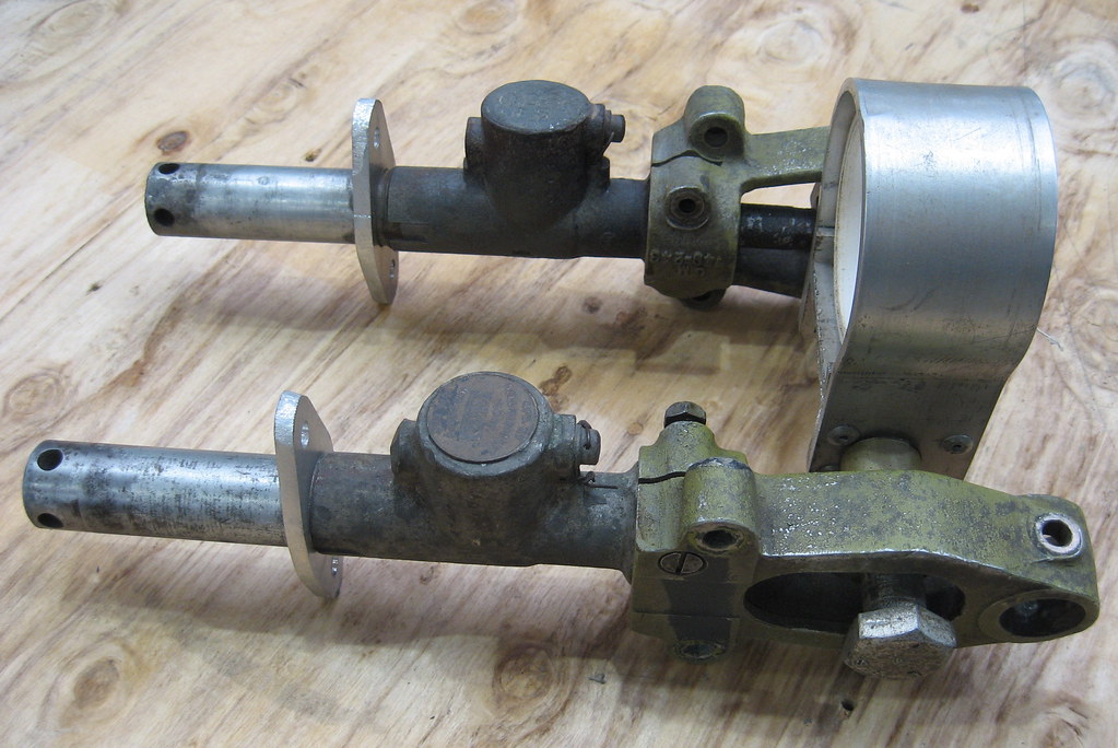 carrier_front_assembly carrier_front_assembly by Ron Wilson, on Flickr Andy from our Tramways workshop had earlier, kindly completed a set of replica gunsights for the Sunderland, so one of those will easily clamp on the top as the finishing touch. As for the replica Browning, that’s still a work in progress but will soon have its basic shape for a test fit. |
|
|
|
Post by emron on Jun 1, 2023 12:27:25 GMT 12
The VHF radio is now back on its shelf and all the cables plugged in and clipped back in place against the fuselage. The camera and drive motor have been brought aboard and also now in their stowed positions. Yesterday, I finished repairs to the small wooden grid to the side of the camera hatch, where the hatch rests when it's removed from the opening. I had previously glued up the vertical battens, so then screwed on two new rungs to replace missing ones. I continued to re-attach backing plates and wiring at the camera station and that just leaves a few more clips and screws before they’re done. Some minor metalwork repairs are necessary before we can fit the row of stowage bags (for the camera leads) that will complete the setup. I hung the G4B compass sensor unit back on its overhead shelf aft of the crew door and next time I’ll re-fit the blackout blinds for the two ceiling portholes. While I was working above the camera hatch, I noticed that the two sockets that secure the flare chute in position were a little worse for wear. They were soon unbolted and now both have been repaired. I had to remove a crusty layer of corrosion that had built up between both of them and the floor frame. One of the side holes had been bored out oversize so I plugged the hole and redrilled and tapped to the original 2BA. One locking screw was broken and the other lost so I adapted a couple of wing nuts to suit.  flare_chute_sockets flare_chute_sockets by Ron Wilson, on Flickr |
|
|
|
Post by emron on May 25, 2023 16:50:32 GMT 12
The VHF radio is now re-assembled and the paint left to dry. Another long-buried item that’s come to the surface of the to-do shelf is the fuel jettison panel. The fuel jettison levers are located at top centre of the Sunderland’s windscreen, forward of the trim tab controls. Once painted the panel’s ready to be screwed back in place.  fuel_jettison_panel_a fuel_jettison_panel_a by Ron Wilson, on Flickr  fuel_jettison_panel_b fuel_jettison_panel_b by Ron Wilson, on Flickr |
|
|
|
Post by emron on May 23, 2023 12:15:47 GMT 12
The main difference between the TR1934, 1935 and 1936 models is their frequency range:
TR1934; 100 to 125 MHz (Mc/s).
TR1935; 125 to 150 MHz.
TR1936; 115 to 145 MHz.
In the case of the RNZAF Sunderlands, the Nov,1951 diagram of A.P.1566E showed 1x TR1934 and 1x TR1935 fitted, but in the March,1953 supplement this had changed to 1x TR1936, which is what I gather they carried until retirement.
To Wayne: If you have located a source of crystals, I’d be interested to learn. MOTAT’s TR1936 may still have the correct combination fitted. I’ll check it tomorrow.
|
|
|
|
Post by emron on May 21, 2023 20:54:16 GMT 12
After a few visits back to the Hastings to compare with the real thing, the reworked front panel for the TR1936 is now ready to paint. I fitted a two-pin core to the power socket, salvaged two 12-pin sockets from surplus Marconi comms boxes and converted one of them with a male core from a spare plug. Then I made a copy of the triangular raised side panel that the 3 right hand sockets are installed in and re-positioned the other two sockets. As a result of those changes, I ended up cutting out a new front plate now slightly wider and with the correct hole locations. When the replica's back together it will be hard to tell the two apart.
|
|
|
|
MOTAT
May 17, 2023 16:46:27 GMT 12
Post by emron on May 17, 2023 16:46:27 GMT 12
Thanks Mike, email now sent.
|
|
|
|
Post by emron on May 11, 2023 20:27:08 GMT 12
Rain interrupted play yesterday, but I was able to swap out the aerial socket on the TR1936 and remove the worst of the corrosion from the aerial plug. After cleaning off paint over-spray from the other plugs and cables, all four connected up well. Next time I’ll take the radio back to the shop for some further refinements and finish off securing the cable clips and bindings. Then I can move back to the camera bay. I’ve thought of a use for the second wedge plate that I started, so it wasn’t wasted effort. We have a spare camera intervalometer which I can position near to the camera. Here’s the completed base plate and wedge with the intervalometer.  intervalometer_wedge_plate intervalometer_wedge_plate by Ron Wilson, on Flickr |
|
|
|
Post by emron on May 9, 2023 20:31:21 GMT 12
Welcome to the Forum.
I recommend you and other members pay a visit to Allan’s Virtual Radio Museum: radiomuseum*co*uk.
He has a gallery of images of other STC radio models TR1985 and civil STR.9-X, which I understand are similar, along with technical info and circuit diagrams that you should find useful.
Looking forward to photos of your completed display.
|
|
|
|
Post by emron on May 7, 2023 18:21:58 GMT 12
There have been some pleasing developments. Talking further with Dennis about the radio cable, he thought it was unlikely that an extension would have been used and suggested that I try to re-route the aerial cable to see if it then reached. Today I found that I could pull down more that was bunched up in the fin and was then able to lay it close to the front panel! I haven’t seen any sign of the genuine socket, so will make do with a UHF type as below, and with a simple sleeve in between. I’ve also been puzzling over the layout of the camera wiring and accessories. After consulting the basic diagram in the manual and comparing bolt holes in the frames, I finally worked out the correct position of the three mounting plates and the electrical wiring loom, so I’ll be able to secure them in place next time. I was missing one wedge plate to mount the camera motor on, so began to make one. But before I’d finished, I was going through a box of miscellaneous parts in the galley and what did I find in the bottom! Anyway, the original is now painted and back in place too. I’ve kept an eye out for a flexible drive shaft for the camera but no success so far. I’ve repurposed another type also using a simple adapter as seen on the right. That will suffice until a genuine part comes to light.  cable_adapters cable_adapters by Ron Wilson, on Flickr |
|
|
|
Post by emron on May 3, 2023 18:00:42 GMT 12
That's interesting, so the antenna cable has a coax connector that isn't a Pye one. I'll have to have a nosy at our TRs as well and see what they are fitted with. We've got loads of Pye sockets so let me know if you go down that track and have trouble finding one. Here’s the TR1936 aerial socket.  aerial_socket aerial_socket by Ron Wilson, on Flickr Front and back view of the aerial cable plug in the Sunderland. 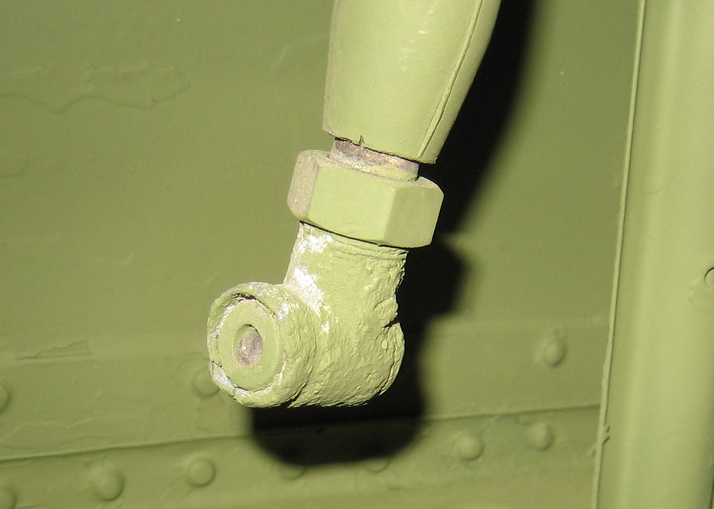 plug_front plug_front by Ron Wilson, on Flickr  plug_back plug_back by Ron Wilson, on Flickr Same push-in style plugs I’ve found; straight one on left is marked 10H/18588, elbow type on right marked 10H/3931.  coax_plugs coax_plugs by Ron Wilson, on Flickr |
|
|
|
Post by emron on May 1, 2023 15:47:50 GMT 12
Thanks for the offer, Alex. The plug on the aerial cable in the Sunderland is too badly corroded to identify. It will also need an extension cable to reach the radio. I’ll check out the Hasting’s set up again on Wednesday and get a close up of the socket. The dummy panel already has a Pye plug filling the hole, so it might be easiest just to replace it with a Pye socket, if I can find one of them. Then I can use a cable with Pye plugs as an extender. We've got a selection of those.
|
|


